

S T A R T H E R E
'Different Chokes' for 'Different Folks'
A Rose is a Rose is a Rose, but an RF-Choke is not an RF-Choke is not . . .
There are many different types of RF-Chokes, some are more simple, some are more complex. Which one(s) you need depends on which problem(s) you are addressing, how much power you run, which antenna you are using, which band(s) the antenna works on, etc., etc.
This "sounds" complicated, but it is not really complicated. If you can read and understand plain English, after reading the next couple of pages you will understand enough to make inteligent purchasing decisions...or even build your own. RF-Choke.
IMPORTANT DEFINITIONS AND
THINGS YOU MUST UNDERSTAND
BEFORE WE BEGIN . . . let's first make sure we all understand one of the most important, yet most mis-understood points about BALUNS and RF-CHOKES:
The meaning of "Balanced" (?)
1) "Balanced" with Respect to Transmission Lines:
We generally think of a transmission line as being the "feedline" feeding the antenna with RF Power. That is not quite right. RF current does not just flow from the transmitter, along the transmission line and "to" the antenna, it flows "through" the antenna . . . and returns through the transmission line to the transmitter's ground. So there is current flowing in both directions. In an ideal case, the level of current flowing at any point along one wire of the transmission line is equal to and opposite in polarity to the current flowing in the other wire of the transmission line.
- COAX Transmission Line: Coax has an inherent feature that all RF Current normally flows inside of the coax, regardless of what is going on, in the outside world around it. RF Current is high frequency alternating current (AC) so it sometimes positive and sometimes negative.
In an ideal case, all current flowing through the shield is flowing on the inside surface of the shield of the coax. This is due to "Skin Effect".
Differential current only flows INSIDE of the coax, so the current flowing through the shield is actually flowing along the inside surface of the coax.
At RF frequencies, the RF current actually sees the shield as two wires, not just one. It sees the inside surface and the outside surface.
When current flows along the outside (outer surface of the shield), it is known as Common Mode Current (CMC). When that happens, the feedline itself radiates as if it were part of the antenna.
An unbalanced coaxial transmission line should always have a balance of current with all current flowing inside of it and no current flowing along the outside of the coax shield. When that is the case, we are happy campers.
Unfortunatley the return current seeing two paths (inner and outer surface of the shield) has no way of knowing which path to follow and will typically split and follow both paths. At that point, with current flowing on the outside of the coax, we have Common-Mode-Current and the transmission line becomes a radiator.
- Open-Wire (Balanced) Transmission Line: At any point along the transmission line, the current flowing on one wire of the feedline is equal to, but opposite in polarity to the current flowing on the other wire of the feedline. This is the "balance" we refer to in Open-Wire Feedlines. As long as this balance is undisturbed, the feedline will not radiate any significant amount of power. If we disturb this balance, the feedline will begin to radiate, just as if it were part of the antenna.
- BALUN: A TRANSMISSION LINE ACCESSORY (NOT ANTENNA!)
A BALUN is a device associated with a transmission line. It is NOT an antenna accessory!
If you check the "ARRL Handbook", you will find ALL of the balun information in the section on Transmission Lines, NOT in the Antenna section. It is difficult to even spot the word "BALUN" in the Antenna section of the book.
Most people believe the purpose of the BALUN is to match unbalanced transmission lines to a balanced antennas. THIS IS TOTALLY WRONG.
A BALUN does not 'match' anything.
Instead, it is a device for preventing RF-Current from flowing along the outside surface of the coax shield. (please read that again)
This is the most important job of the BALUN
and why we use a BALUN in the first place.
In doing so, it forces the current to flow inside of the coax (where it belongs), along the inside surface of the coax shield, enabling the differential current, (explained above), to maintain its balance.
"THIS" is the "Balance" that the "BAL" in BALUN is referring to!
Certain types of baluns combine a balun with a transformer. These are called "transformer baluns" (i.e., 1:4, 1:9) etc. However their choking ability is significantly worse than that of a 1:1 balun.
There are other types of "so-called" baluns which are good transformers but very lousy baluns - the worst being the single-core 4:1 Guanella (current) balun. Unfortunately there are many commercial BALUN suppliers still selling this inferior product. Baluns will be handled in more detail in another section of my web.
More Info: See: BALUNS: What They Do And How They Do It
2) "Balanced" with Respect to Antennas
When we talk about a "balanced antenna", we are not referring to a balance in current or balance in voltage, nor even to a balance in its physical shape.
We are talking about a 'balance of impedance' to the reference plane (ground) of each half of the antenna!
It is the imbalance of impedance between the two halves of the antenna that CAUSES an imbalance of current, not the other way around!
This imbalance of current then causes the feedline to radiate, and other bad stuff.
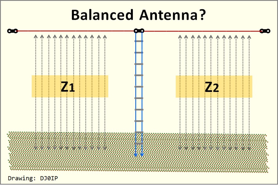
NORMALLY, when we think of a dipole, especially when it is fed with a Balanced Feedline such as Open-Wire, we consider this antenna to be balanced. Physically it is balanced. But is it electrically balanced?
Unless we mount the antenna high in the air, several wavelengths above ground, there is always capacitive coupling between the wire legs of the antenna and ground. this coupling affects each leg's impedance.
The relationship of Z1 to Z2 determines whether the antenna is balanced or not..
If it is truly balanced, then Z1 = Z2. If not, we have an imbalance.
In real-life, it is rare that Z1 = Z2.
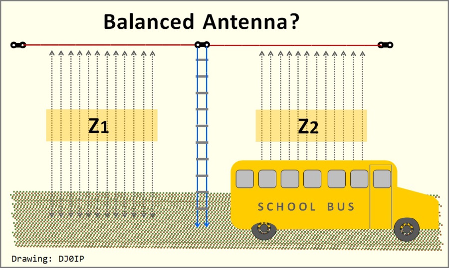
SOMETIMES "SHIT HAPPENS":
Is this antenna still balanced to ground?
In reality, shit is happening all the time with every antenna installed here on mother earth!
It isn't always this bad but it is rare indeed that Z1 = Z2. Forget "balanced"!
Guess what that does to the current?
I once had an 80m dipole fed through a 1:1 Current BALUN, with one of its legs high and in the clear, but the other leg (same height above ground) running over and close to the roof of my house. Although I had used this same antenna at a dozen other locations and always had a low SWR with it, at this QTH I could not get the SWR under 2:1. Eventually I guessed what was happening. I began shortening the length of the leg running over the house and the SWR began to drop. I tuned its length for minimum SWR.
So balance does not depend on the physical shape of the antenna alone. Many other factors may influence its electrical balance, causing a minor or even a significant imbalance in the impedances to ground, thus causing an imbalance of current to flow.
Furthermore, with multi-band antennas, the balance (or imbalance) can differ vastly from one band to another, so the trick of shortening one side of the antenna often does not help.
This imbalance of current flow at the antenna's feedpoint often causes several unwanted dirty things to happen:
- Some of the return current flows on the outer surface of the coax, causing it to radiate.
- This distorts the normal radiation pattern of the antenna.
- It causes radiation near the shack and into places we don't want it to go... such as to the neighbors' houses!
- RF current can enter the shack.
- Burn baby, burn! Burn your lips on the mic, your fingers on the key or chassis of the radio. etc.
- Power and SWR readings on your insturments often are inacurrate.
- Sometimes your equipment will fault and shut down.
This unwanted flow of RF current on the outer surface of the coax, or in the case of Open-Wire feedline, difference in the level of RF current flow on the two wires of the feedline, is what we call
Common Mode Current.
We have two weapons in our arsenal for fighting CMC:
- BALUNs & RF-Chokes
THIS CHAPTER OF MY WEB IS ABOUT RF-CHOKES.
IMPORTANT: The RF chokes shown on the next page are very simple chokes that anyone can build and in many cases, will solve most 'soft' CMC problems.

N E W
OCFD ANTENNA
PRESENTATION


( Info-Only; NO SALES! )
Spiderbeam on Facebook:


BRAND NEW
from Spiderbeam:

Mini "SOTA" Pole
by Rob Sherwood NC0B

(AUF DEUTSCH)


Spiderbeam FG Pole

Photo: Nischal Nethrananda

A fun film about
Ham Radio Outdoors
(not just in Tenerife)
(English & German)


(nearly) Invisible Pole

An Aerial-51
Sponsored Expedition:
INTRODUCING
Special purpose Aerials:

Ultra-Lightweight antennas for expeditions and stealth applications.
+
(other)
---------------------
UPDATES:
|
|
-----------------
LL-TUNER "S-MATCH"
added to my
symmetrical tuner page.
----------------------
PROGRESSING:
LOTS OF NEW CONTENT IN THE SECTION:


Since JAN-2013
*******************