
8-BAND HORIZONTAL LOOPs
1) Horizontal QUAD LOOP: built by Everett Sharp, N4CY (ex-N8CNP).
2) Horizontal DELTA LOOP: built by Lucas, KN4MEJ
3) Horizontal DELTA LOOP: built by Leslie, VE9ASN
DISCLAIMER:
I have not personally built or used any of my these three antenna described here.
However, I have used several Horizontal Quad Loops fed with Openwire Feedline and as you will see on another page in my web, I have declared it to be my favorite all band antenna. See: My Favorite All-Band Antenna
1) THE QUAD LOOP (N4CY):
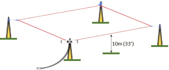
8-Band Coax-Fed "Lazy" Loop
Bands: 80/40/30/20/17/15/12/10m
Length: 1 Wavelength (275 ft.)
(68' 9" per side)
Height: 30 ft. at each corner
Balun: 4:1 Dual-Core Guanella*
2x FT-240-43 (15 turns)
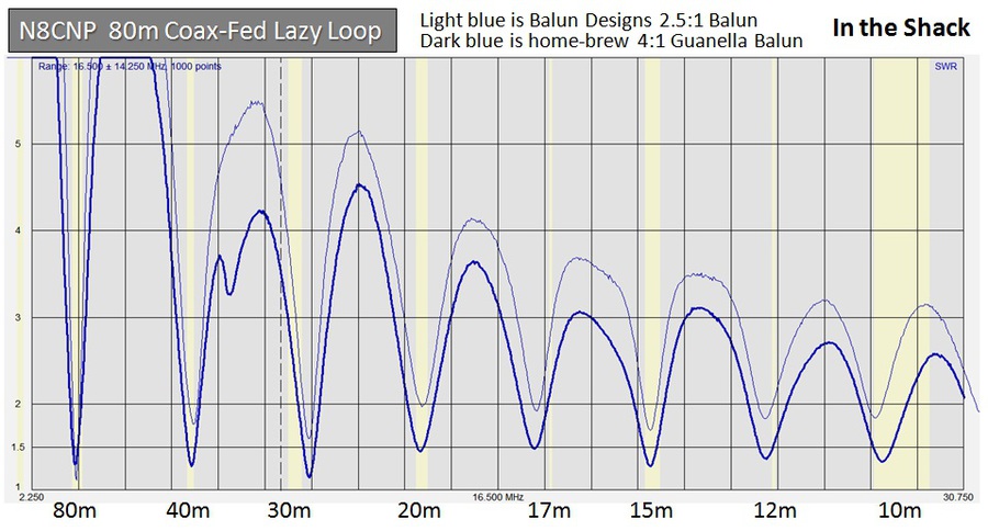
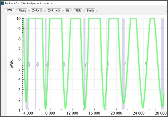
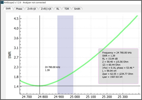
SWR Across the HF Bands
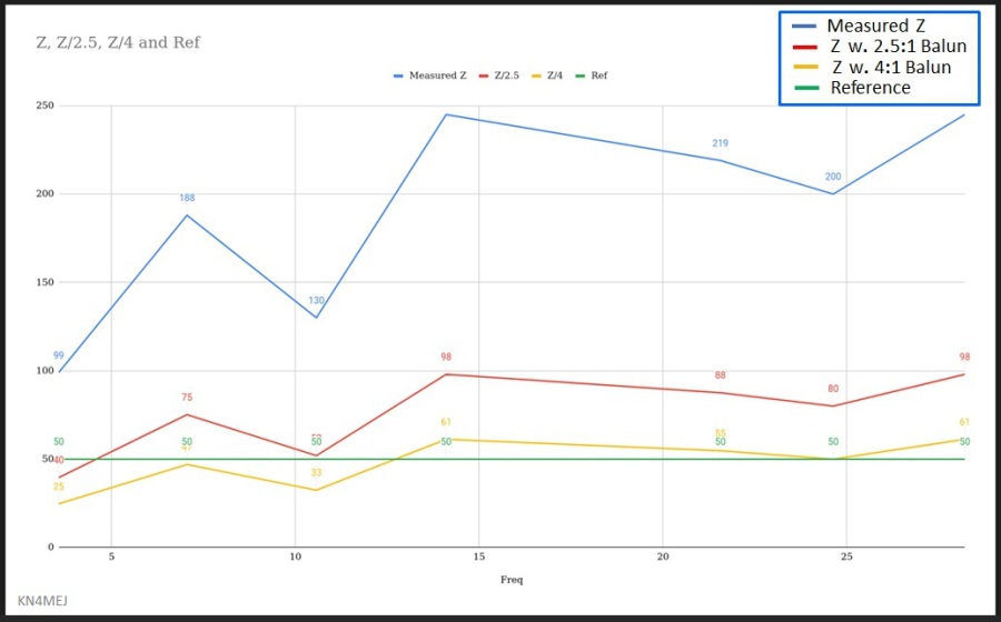
*Everett initially tried a 2.5:1 (125 Ohm) commercial balun by Balun Designs. The results are shown below in light blue. Then he replaced it with his 4:1 home-brew balun which improved all bands (except 80m) considerably. 80m is still very good.
Measurements were taken with a RigExpert AA-170.
SWR measured in the Shack:
SWR measured with 50 ft. of RG8X, using A RigExpert AA-170:

Common Mode Current can easily skew SWR curves. Transmission Lines transform SWR values.
Measuring at the feedpoint would be a better method but Everett is 72 years old, so I doubt he will climb a ladder. The AA-170 does not have an OSL feature. [DJ0IP]
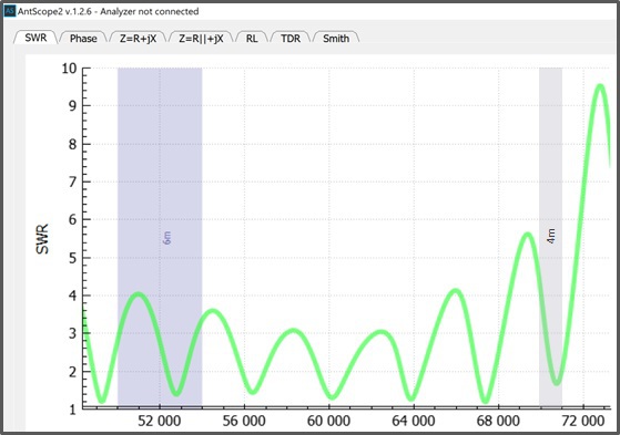
In order to determine this, short of buying an analyzer that can zero out the coax, we can measure using different lengths of coax. When doing so, we will look for changes in the apparent resonant frequency (i.e. point of minimum SWR on each band), as well as any significant changes in the magnitude of SWR. [DJ0IP]
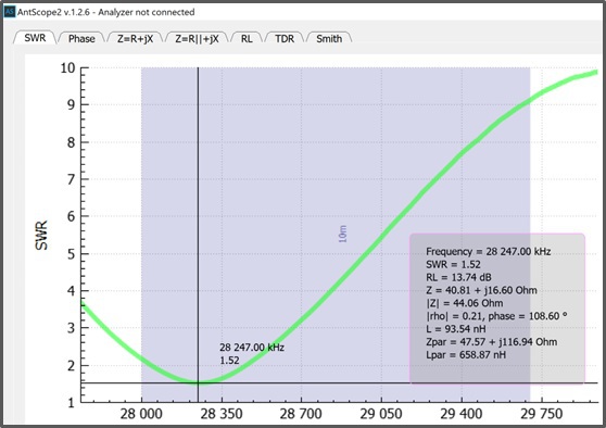
SWR Comparison with different lengths of Coax:

Comparing these two graphs strongly suggest that there is very little Common Mode Current at work here. When just a little CMC is present, what you see when changing coax lengths is a change in the apparent resonant frequency and also better looking bandwidth. That did not occur here, which IMO indicates that there won't be problems with CMC. [DJ0IP]
If the SWR level were significantly affected due to transmission line transformation, then the level indicated on the band(s) affected would be quite different from one graph to the next. This is not the case. Therefore it is a fair assumption that the values shown here are very close to what we would find at the feedpoint. [DJ0IP]
I don't know why the 4:1 balun worked out better than the 2.5:1 baln on my loop. I am feeding the loop in a corner, which should be 100 Ohms - more or less. On another installation, the results might be different. [N4CY]
DISCUSSION:
Hopefully Everett has found repeatable results. If so, this antenna is going to make a lot of people very happy.
My personal experience using the openwire-fed version of this antenna has been overwhelmingly good - as you can read on some of the other pages here on my web site.
My own openwire-fed versions of the full-wavelength loop antenna was fed with a high-power ANNECKE SYMMETRICAL KOPPLER, which is an improved version of the old Johnson Viking Kilowatt Matchbox.
These are no longer built today, are terribly expensive on the used market, and next to impossible to find.
In the meantime I have switched to using an unbalanced antenna tuner with a good 1:1 Guanella (current) balun between it and the feedline.
The coax-fed version shown here would be a very welcome addition to anyone's antenna farm and most likely will not require a tuner, or if it does, then any general purpose tuner will do the job.
IF ANYONE ELSE TRIES THIS ANTENNA, PLEASE SHARE YOUR RESULTS WITH US! TNX.
===============================
2) THE DELTA LOOP (KN4MEJ):
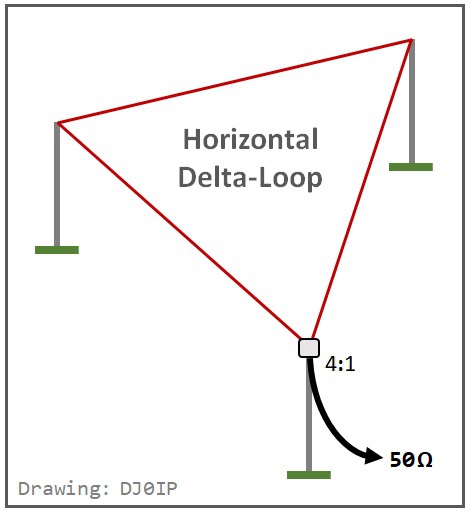
7-Band Coax-Fed "Lazy" Loop
Bands: 80/40/30/20/17/15/12/10m
Length: 1 Wavelength (270 ft. / 90' per side)
Wire: 14-AWG (DX-Eng. Premium Ant. Wire)
Height: 30 ft. at each corner
Balun: Dual-Core 4:1 Guanella Balun
(2x FT-240-43 with 12 turns of 12-AWG "GXL" wire on each core)
Choke: 3x 1:1 Guanella chokes in series
(K9YC) wound with 10 ft. of RG400 on
FT-240-31 Toroids, with 16, 14, 11 turns
SWR Curve (w. 4:1 Balun):
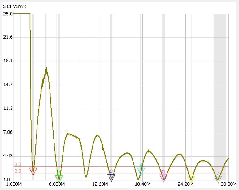
As can be seen from the SWR curve (above), the SWR is quite low on all HF ham bands.
Lucas began by measuring the actual feedpoint impedance with a NanoVNA.
He then measured it again with a 2.5:1 balun and with a 4:1 balun:
Although the SWR levels of the 2.5:1 balun within the ham bands are low enough to be used with an antenna tuner, they are not as good as the SWR levels with the 4:1 balun.
We conclude from this Delta Loop antenna, and the Quad antenna above that the full-wavelength 80m loop is best fed with a 4:1 balun.
ADDITIONAL INFORMATION:
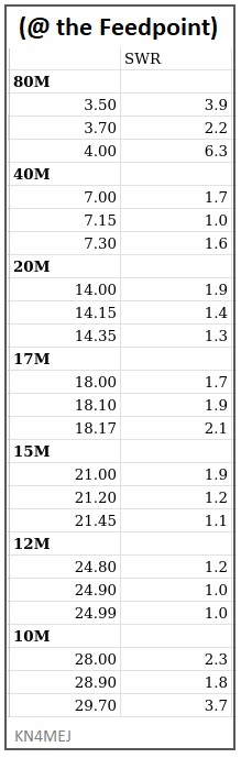
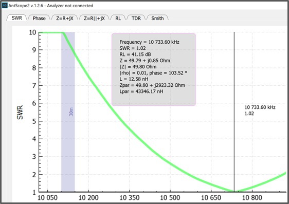
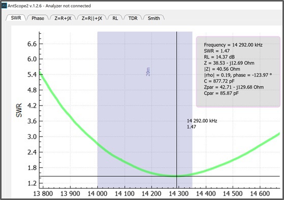
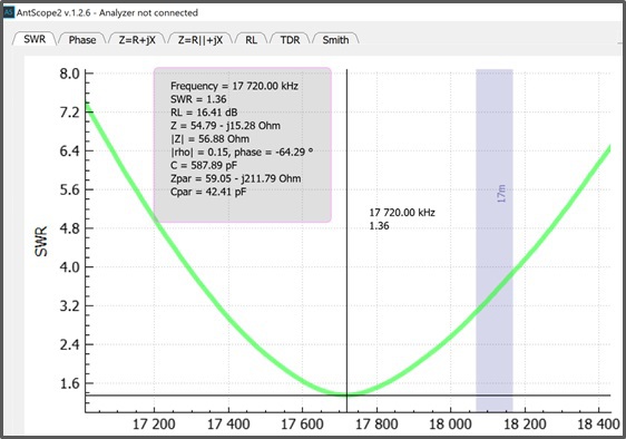
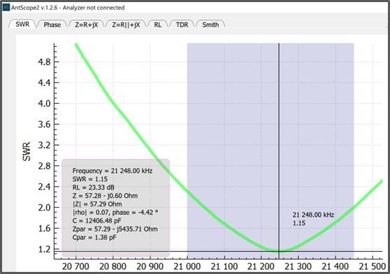
SWR ACROSS THE HF HAM BANDS:
The chart on the right shows the SWR levels as measured across the HF ham bands with a NanoVNA analyzer.
All bands (except for 80m and 10m) can be used with most transceivers without an antenna tuner.
On 80m and 10m, the built-in ATU's in most transceivers is sufficient for matching 80m and 10m (exception: Icom Transceivers).
REALITY:
For installations using typical "City Lengths" of coax (i.e., up to 100 ft.), the additional loss in good quality coax compared to using balanced-feedline is so low that nobody on the planet can hear a difference or see a difference at the S-Meter at the other end of the QSO. [DJ0IP]
------------------------------------------------------------------------------------
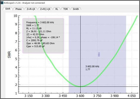
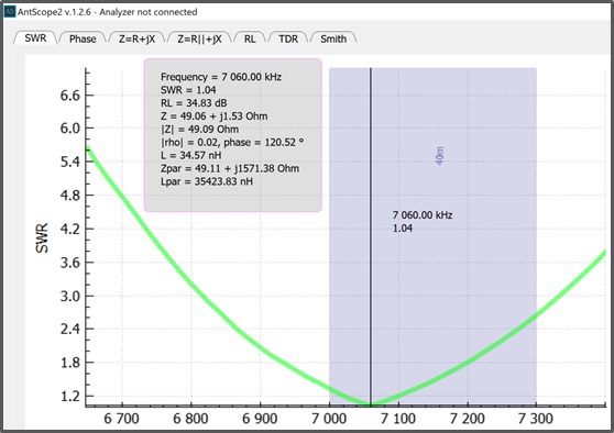
BALUN COMPARISON (by band) @ THE FREQUENCY OF MINIMUM SWR:
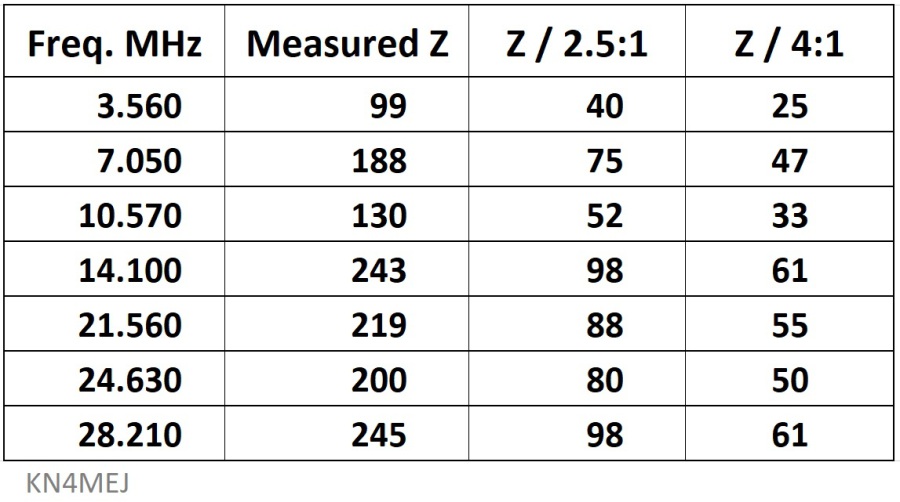
Note: Measured Z is the actual impedance measured at the antenna.
. The balun columns show: Measured Z/2.5 and Measured Z/4.0 .
===============================
3) THE DELTA LOOP (VE9ASN):

7-Band Coax-Fed "Lazy" Loop
Bands: 80/40/30/20/17/15/12/10m
Length: 1 Wavelength (80m)
Wire: ?-AWG ( )
Height: 40 to 45 ft.
Balun: Hybrid Balun (see below)
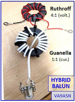
4:1 HYBRID BALUN (designed by DJ0IP)
4:1 Ruthroff (voltage) Balun
11 turns of twisted pair wire (source: DX-Wire)
Teflon-insulated, silver-plated 18-AWG solid copper wire
1:1 Guanella (current) Choke-Balun
16 turns of DXW-50 coax (source: DX-Wire)
Teflon-insulated, 50 Ohm (dia. 4mm)
SWR Curves (by band):
===============================
DISCUSSION:
ADVANTAGES BALANCED-LINE-FED:
- Lower loss with extremely long runs of feedline.
- The 'exact' length of the antenna is non-critical. There is no need for pruning for lowest SWR.
DISADVANTEGES BALANCED-LINE-FED:
- An antenna tuner is always required on ALL bands.
- Using balanced-line feedline can present problems, especially when the feedline must go around corners.
- Balanced-line feedline can be more difficult to bring into the house.
ADVANTAGES COAX-FED:
- NO ANTENNA TUNER REQUIRED for most of the HF bands.
- Feeding with coax is often easier, especially when the feedline must go around corners.
DISADVANTAGES COAX-FED:
- The length of the antenna is highly critical. It must be trimmed exactly for lowest SWR.
- For very long runs of feedline, coax has more loss.
- Good quality coax is more expensive than balanced-line.
IF ANYONE ELSE TRIES THIS ANTENNA, PLEASE SHARE YOUR RESULTS WITH US! TNX.

N E W

A Short Video by W8JI
N E W
OCFD ANTENNA
PRESENTATION


( Info-Only; NO SALES! )
Spiderbeam on Facebook:


BRAND NEW
from Spiderbeam:

Mini "SOTA" Pole
by Rob Sherwood NC0B

(AUF DEUTSCH)


Spiderbeam FG Pole

Photo: Nischal Nethrananda

A fun film about
Ham Radio Outdoors
(not just in Tenerife)
(English & German)


(nearly) Invisible Pole

An Aerial-51
Sponsored Expedition:
INTRODUCING
Special purpose Aerials:

Ultra-Lightweight antennas for expeditions and stealth applications.
+
(other)
---------------------
UPDATES:
|
|
-----------------
LL-TUNER "S-MATCH"
added to my
symmetrical tuner page.
----------------------
PROGRESSING:
LOTS OF NEW CONTENT IN THE SECTION:


Since JAN-2013
*******************