
Antenna Tuners
High Power Symmetrical Matchboxes
MARKET OVERVIEW:
BUYER BEWARE !
There are a lot of high power asymmetrical matchboxes on the market which are marketed for matching symmetrical antennas. YES they work, but NO, they don't always work as well as a symmetrical matchbox.
I addressed this topic separately on a previous page, SYMMETRICAL MATCHBOXES.
See the bottom of that page for more info on this.
THE MARKET SITUATION:
- If you live in Europe, you have many alternatives available.
- If you live in the North America, you have some good choices but your choices are limited.
- Unfortunately I do not know what is available on the Asian market.
NEW, USED, or HOME-BREW:
You have three sources of high power symmetrical matchboxes.
Unfortunately new high-power symmetrical matchboxes are quite expensive.
Hams in the US will pay a lot less than hams in Europe, but the hams in Europe have a broader portfolio to choose from.
The used market can be a good source for high power symmetrical matchbox, but again, buyer beware. A lot of the old Johnson Viking Matchboxes are pretty corroded inside, and in a sad state of repair. In addition, without a bit of modification, the Johnson is really not a great choice it you want your matchbox to cover a lot of bands.
The Annecke high power Symmetrical Koppler is a much better matchbox, but you will NEVER find one. Annecke built exactly 20 of these units. In addition, a handful of people built home-brew versions using his components. Forget it. You will win the lottery or get struck by lightening before you find one of these for sale!
PRODUCT OVERVIEW:
Here is a list of the High Power Symmetrical Antenna Tuners available on the market.
The list includes tuners which are currently available on the market, as well as a few which are only available on the used market. The S-Match is not available for purchase, but is very simple to home-brew.
*BALANCED TUNERS:
- Annecke Symmetrical Koppler ............... Link-Coupled
- Annecke Modular Symmetrical Koppler... Link-Coupled
- Annecke Dual Switched-Inductor .......... Balanced-Switched-Inductor
- Antec UT-1 .......................................... Link Coupled
- Christian Koppler (DL3LAC) .................. Balanced-L
- DECCA KW-109 SUPERMATCH .............. Z-Match (Link-Coupled)
- HamWare AT-615B ............................... Ballanced-Pi
- Harvey Wells Z-Match ............................ Z-Match (Link-Coupled)
- Johnson Viking Kilowatt Matchbox ........ Link-Coupled
- LINEAR AMP UK LA-STWM..................... Inductively Coupled
- LL-Tuner (PA0LL) ................................. Balanced-Pi
- LL-Tuner S-Match (PA0LL) ...................... S-Match
- MFJ-976 ................................................. Balanced-T
- Palstar BT-1500A ................................... Balanced-L
- S-Match (PA0FRI) .................................. S-Match
- TMC-TAC-1 ............................................. Link-Coupled
*This list does not include Asymmetrical Tuners which use a balun to match balanced loads.
[ Legand: Available New / Available Used (only) / Home Brew (only) ]
* * * * * * * * * * * * * * * * * * *
AVAILABLE ON THE NEW EQUIPMENT MARKET:
* * * * * * * * * * * * * * * * * * * * * * * * * * * * * * * * * * * * * * * * * * * * * * * * * * * *
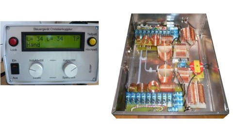
Christian Koppler
Yes, that is its real name.
This is a Remote Matchbox, meaning it has a seperate RF Deck and Control Unit. It uses an RS-232 (serial) cable to connect the two components.
This is a Balanced L-Network matchbox.
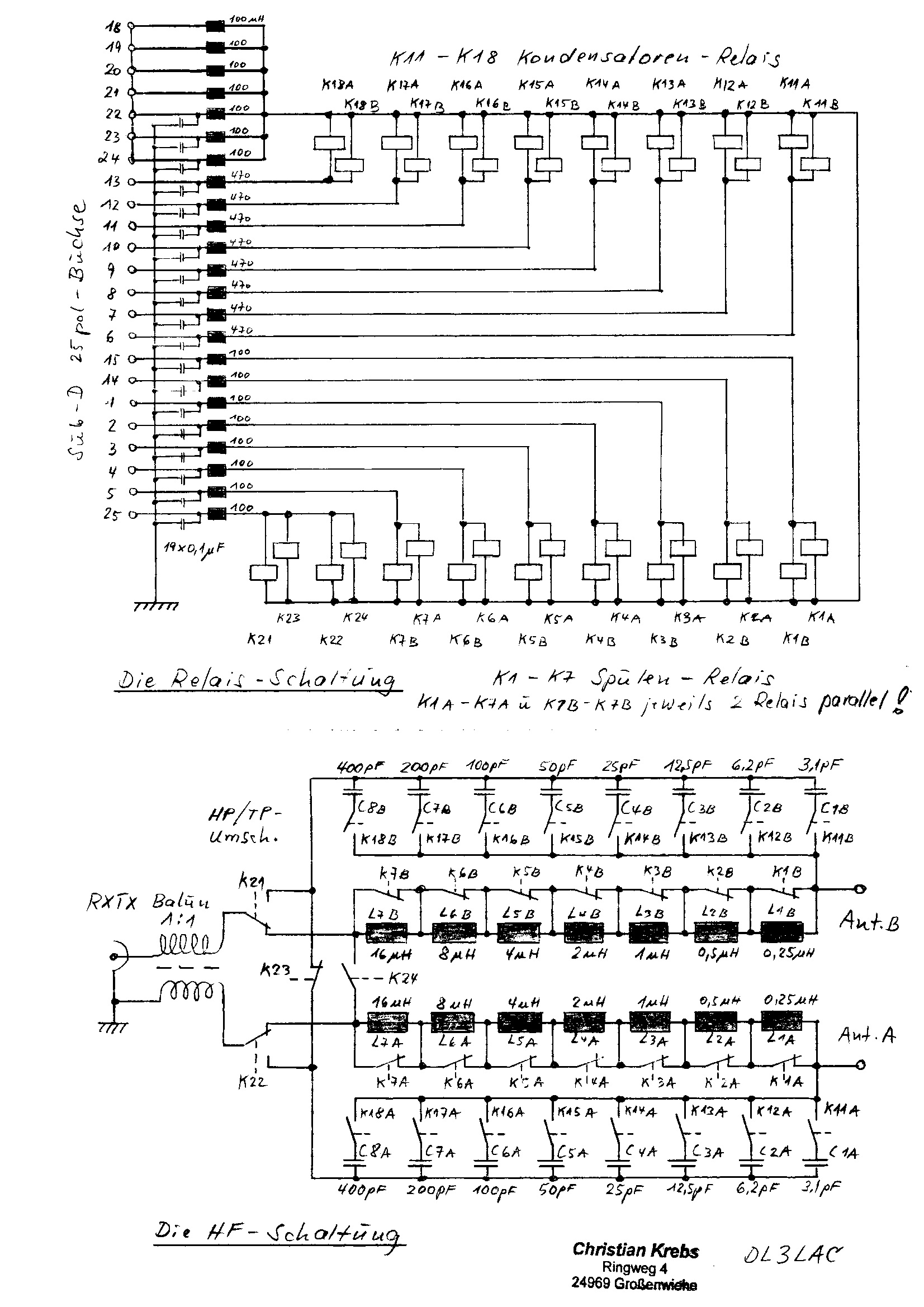
The circuit consists of 2x each of the following:
- Fixed inductors, switched with relays in 128 steps, 0.25 uH per step, from 0.25 to 32 uH. All inductors are air-core coils. A toroid is only used in the 1:1 balun on the TX side.
- Fixed capacitors, switched with relays in 256 steps, 3 pF per step, from 3 to 800 pF. The capacitors are rated 4kV.
This matchbox circuit can be switched from High-Pass to Low-Pass, which is unique among Balanced L-Network matchboxes.
There are no memories, so this is a manual tuner, and a very good one at that. Its biggest advantage is, you can run openwier from the antenna to a point near the house, and then a well matched coax cable into the hourse. The only disadvantage is, you need a second cable for control.
Here is the Schematic:
* * * * * * * * * * * * * * * * * * * * * * * * * * * * * * * * * * * * * * * * * * * *
.
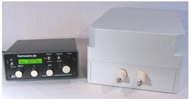
HamWare AT-615B
Like the Christian Coupler, this is a Remte Matchbox. However it differs in that it is a Semi-Automatic matchbox. You have to tune the matchbox manually at several points on each band, and store each result. After that the matchbox will monitor the frequency and automatically jump to the correct settings.
UNIQUE: This is a Balanced-Pi Matchbox. It has a broad matching range and excellent efficency. Unfortunately its price is also unique. This is possibly the most expensive matchbox on the amateur radio market.
* * * * * * * * * * * * * * * * * * * * * * * * * * * * * * * * * * * * * * * * * * * *
.

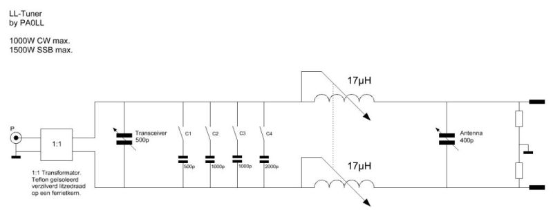
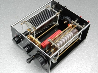
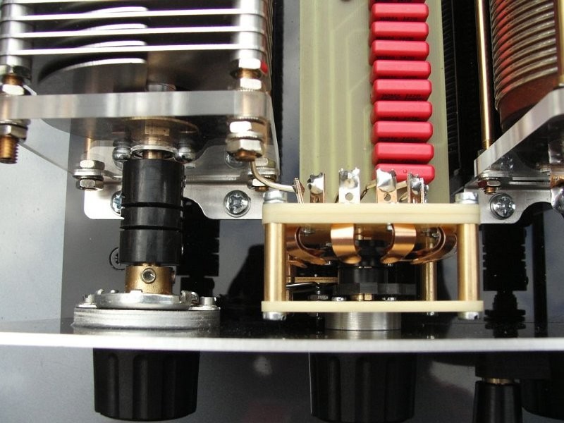
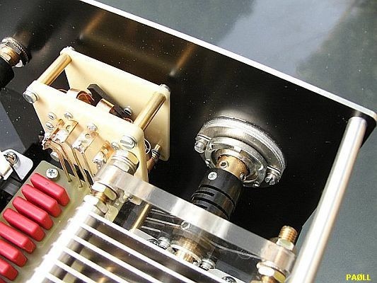
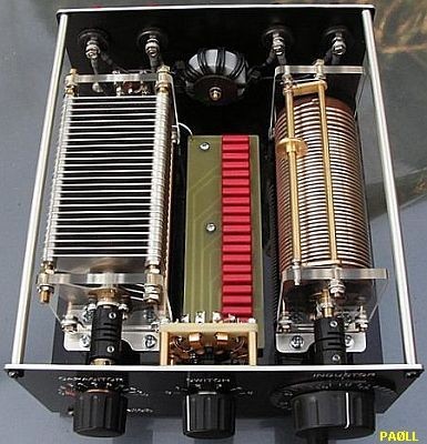
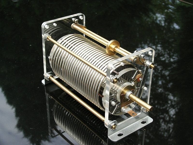
LL-Tuner
The LL-Tuner is probably the world's most expensive manual balanced matchbox. It is also one of the most beautiful matchboxes on the planet.
This version of the LL-Tuner uses a Balanced Pi-Network circuit. I have not seen any 3rd party tests of this matchbox, but judging by its design, it should be able to efficiently match a very broad impedance range.
It is rated for 1500 Watts PEP SSB output, and 1000 Watts CW.
One thing is for sure: if I win the lottery, I will buy one of these!
I don't have an instruction manual for this matchbox but I do have a schematic diagram.
As you can see, in addition to the two variable capacitors, it also has 4 switched capacitors in parallel with the variable capacitor on the TX side. This assures that it can match very high impedances.
Here is the Schematic:
JPG-Datei [16.2 KB]
* * * * * * * * * * * * * * * * * * * * * * * * * * ******** * * * * * * * * * * * * * * * *
LL-TUNER: S-MATCH
In addition to the LL-Tuner (Ballanced-Pi Matchbox) described above, Kees also offers an S-Match. It is built to the same standards as the LL-Tuner, but encorporates fewer components and is therefore somewhat cheaper.
Add this one to my (dream) wish list please!
More general details on the S-Match are at the bottom of this page.
I don't yet have any experience with this technology but I am currently building an S-Match and will test it later this summer (2014).
For more information, see: http://www.lltuners.nl/index.php/ll-s-match.html
I do not have a manual for this one, but the important information can be found on the S-Match "Bible" web page of PA0FRI, here: http://pa0fri.home.xs4all.nl/ATU/Smatch/smatcheng.htm
PHOTO GALLERY:

* * * * * * * * * * * * * * * * * * * * * * * * * * * * * * * * * * * * * * * * * * * * * * * * * * * *
.
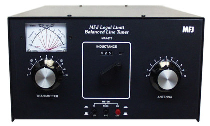
MFJ-976
The MFJ-976 is a high-power Balanced T-Network. Though not cheap, it is the lowest cost high-power balanced matchbox currently on the market.
The T-Network enables a broad matching range, but the efficiency suffers, especially at both ends of the frequency spectrum and impedance range. 80m and especially 160m have high losses with very low impedances. Unfortunately low impedance antennas are what we often encounter on these bands.
Despite this weakness, the MFJ-976 is still a good matchbox. Its matching range extends a bit lower than the Palstar (below), but its losses at that impedance is nearly 50%. It is better to take care that you use antennas which do not have such low impedances.
* * * * * * * * * * * * * * * * * * * * * * * * * * * * * * * * * * * * * * * * * * * *
.
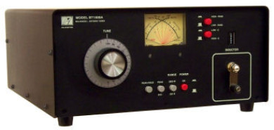
Pastar BT-1500A
This is a very nice implementation of the Balanced L-Network technolgy.
In recent ARRL lab tests, it proved to be very efficient for the ranges tested (up to 800 ohms).
It has a broad matching range on the low bands (through 20m) but is limited on 17 through 10m to just 1000 Ohms.
On the low end, the matchbox only goes down to about 10 Ohms, but regardless of what your matchbox can handle, if your impedance is that low, you should fix the antenna.
Like all Palstar matchboxes, its build quality is excellent. It costs 50% more than its closest competitor, the MFJ-976, but if you can afford it, it is worth the additional cost.
* * * * * * * * * * * * * * * * * * * * * * * * * * * * * * * * * * * * * * * * * * * *
.
* * * * * * * * * * * * * * * * * * *
AVAILABLE ONLY ON THE USED EQUIPMENT MARKET:
* * * * * * * * * * * * * * * * * * * * * * * * * * * * * * * * * * * * * * * * * * * *
.
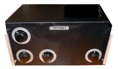 Photo: Alfred Annecke
ANNECKE SYMMETRICAL KOPPLER
This is the ANNECKE SYMMETRICAL MATCHBOX FLAGSHIP!
It is an improved version of the famos Johnson Viking Kilowatt Matchbox.
Its Link-Coupled ciruitry uses huge components; you almost need 2 hands to rotate the bandswitch.
SPECIFICATIONS:
- Bands: 80 - 10m
- Power: 1000 Watts (continuous carrier)
- Impedance Matching Range: 50 to 3000 Ohms
- Size (Width/Heigth/Depth): 50 x 25 x 35cm (20" x 10" x 14") - HUGE!
There were only about 20 of these ever built and basically anyone who owns one never sells it. You are more likely to find Bird Doo in a Kuku Clock than to find one of these for sale on the used market!
Like its little brother the 200w Symmetrical Koppler, this matchbox added taps to the coil and used a 3rd variable capacitor in series with the coax on the transmitter side of the tank circuit. These two mods improve the overall matching range and assur you always get a good match to any antenna, on any frequency.
In my personal opinion, this is the BEST SYMMETRICAL MATCHBOX EVER BUILT.
(I am one of the rare fools who had one and sold it.)
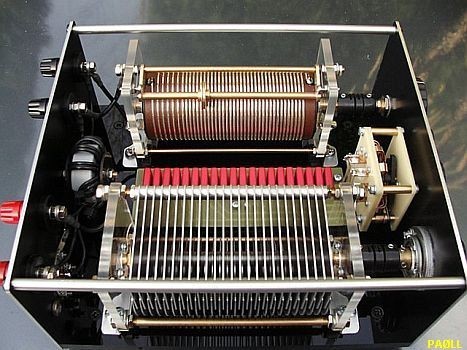
For a closer look at the components used inside this famous matchbox, see the cover of the 1988 Annecke Catalog. (The big coil, switch, and capacitors on the right are the ones it uses.)
You will find the Schematic and internal pictures in the gallery below:


( All Photos: DJ0IP )
After 25 years of searching, I have finally obtained a copy of the original manual for this wonderful matchbox. MANY THANKS TO MARTIN, DK8ZJ, for providing this manual:
.
ANNECKE 1KW SYMMETRICAL KOPPLER.pdf
PDF-Dokument [493.8 KB]
* * * * * * * * * * * * * * * * * * * * * * * * * * * * * * * * * * * * * * * * * * * *
.
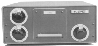 Photo: Alfred Annecke
ANNECKE MODULAR SYMMETRICAL KOPPLER
A Medium Power Balanced Matchbox.
Rated 500w CW, 600w PEP.
(160m limited to 75w SSB/CW)
SPECIFICATIONS:
- Bands: 160m* - 10m
- Power Rating: 500w CW / 600w SSB
- Impedance Matching Range: 50 - 3000 Ohms
- Size (Width/Height/Depth): 30 x 12.5 x 38cm (12" x 4" x 15")
*160m power limited to 75 Watts.
Remember, Annecke rated his matchboxes conservatively. If your antenna did not have too high or too low of an impedance, this matchbox could easily be run at power levels of 800 to 1 kW in typical CW and SSB use.
The Annecke circuitry was tried and proven. On the high end there was the EXPENSIVE Kilowatt Symmetrical Koppler, on the low end the 200w Symmetrical Koppler. Both matchboxes had the exact same circuit but they were worlds apart in power-handling ability and cost.
In addition, most OM who run openwire in Germany do not run the maximum legal power, 750 Watts. Indeed, most run barefoot, or if they run an amp at all, it is typically 500w. Amp.
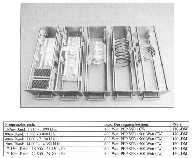
Annecke designed this intermediate Symmetrical Koppler to address this market. Although the circuitry is exactly the same as on the larger matchbox, to keep cost low he used a modular design with plug-in band modules, rather than an expensive band switch.
The advantage of this approach is easy enough to see when you look a the internal pictures of the matchbox. By using band modules, each plug-in module used a link-coupled tank circuit which was custom designed for the frequency range the module should cover.
This is an outstanding symmetrical matchbox for people who don't need more power and don't mind swamping band modules when changing bands.
Its primary limitation was its power level on 160m.
You can view the band modules and the schematic diagram in the gallery below:
* * * * * * * * * * * * * * * * * * * * * * * * * * * * * * * * * * * * * * * * * * * *
.
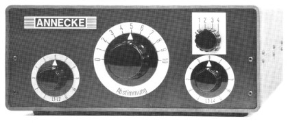 Photo: Alfred Annecke
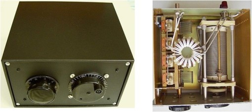
ANNECKE
BALANCED SWITCHED-INDUCTOR
SYMMETRICAL COUPLER (1000 w)
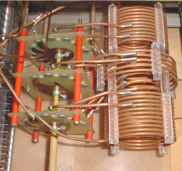
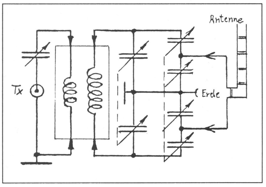
In an effort to make high power symmetrical matchboxes affordable for everyone, Annecke brought out this version in the mid 1990s.
This is Annecke's only symmetrical coupler which does NOT use Link-Coupling.
Instead, this version of Annecke's symmetricl couplers used synchronized switching of 4 inductors, and just one variable capacitor. It also had 3 additional fixed capacitors that could be switched in when needed.
SPECIFICATIONS:
- Bands: 160 - 10m
- Power Rating: 1000w PEP/CW
- Impedance Matching Range: 50 - 3000 Ohms
- Size (Width/Height/Depth): 30 x 12.5 x 42 cm (12" x 5" x 16.5") - very small compared to the BIG ANNECKE!
I used one of these for several years, side by side with my "Big Bertha" Annecke 1KW Symmetrical Coupler (with link-coupling). I can safely state that there is a world of difference in matching ability between the two technologies. Of course there was also a world of difference in the price and size of the two boxes.
In general, this matchbox would match just about anything, but it was not always able to obtain a 1:1 match. Sometimes you had to settle for 1.5 to one, or even slightly worse. Never-the-less, it still worked. The BIG ANNECKE had no problem obtaining a 1:1 match with almost any antenna.
The successor to this version was the Modular Symmetrical Coupler (above). It had a matching range and ability similar to that of the other link-coupled matchboxes, but it could not run full power on 160m as this version does.
Never-the-less, for about $700 this version enabled people with legal power (in Germany) to run openwire-fed antennas.
Schematic below:
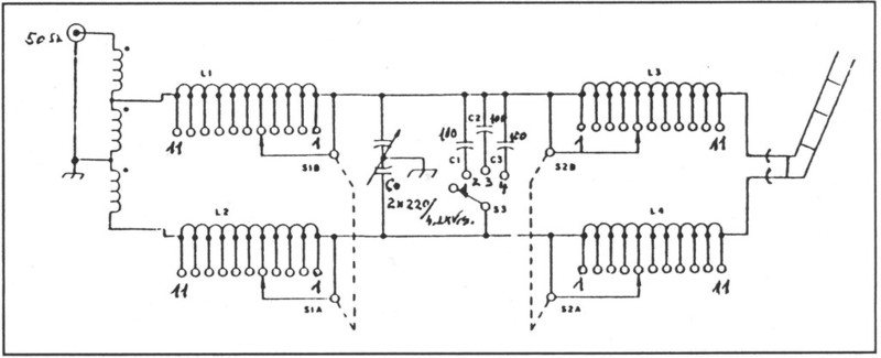
annecke-symmetrisch_v6.pdf
PDF-Dokument [558.2 KB]
.
* * * * * * * * * * * * * * * * * * * * * * * * * * * * * * * * * * * * * * * * * * * *
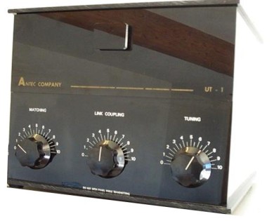
ANTEC UT-1
A Link-Coupled matchbox out of the early 1970's, covering 80-10m. The cabinet was made of Plexiglas.
The top half of the front panel is a removable module which enables access to the coil. To change bands, you pull the module out, manually move taps on the coil (using clips) and then re-insert the module in the tuner. This was very effective, but arguably not very practical.
The matchbox was rated for 1kW Input Power, but from the looks of the size of components, you would not be able to use it at that power level with very high or very low impedances. However it hould have no problem matching impedance extremes - albeit with somewhat reduced power.
* * * * * * * * * * * * * * * * * * * * * * * * * * * * * * * * * * * * * * * * * * * *
.
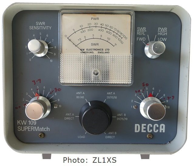
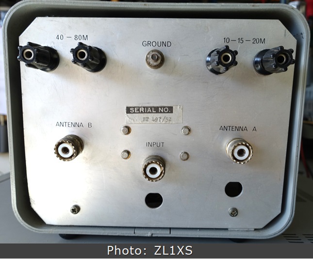
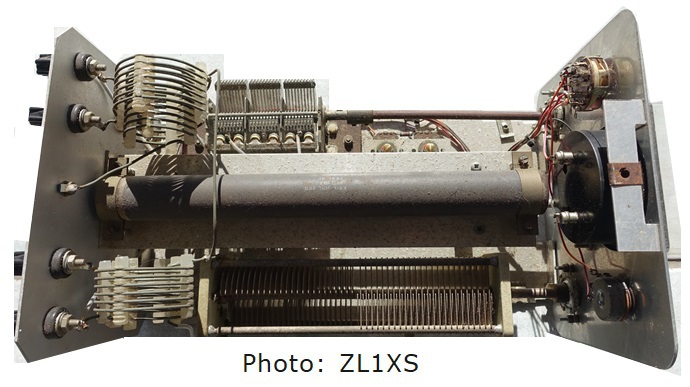
DECCA KW-109 SUPERMatch
This is a classical 2-tank circuit Z-Match, and basically the same circuit as the used in the KW E-ZEE Match. This version can handle more power. How much depends on the impedance of the antenna. As long as the SWR is under about 5:1, it will handle about 400 to 500 Watts PEP SSB out.
I have never seen one of these in real life but I did have its little brother, the KW E-ZEE Match. You can download the instruction manual below:
* * * * * * * * * * * * * * * * * * * * * * * * * * * * * * * * * * * * * * * * * * * *
.
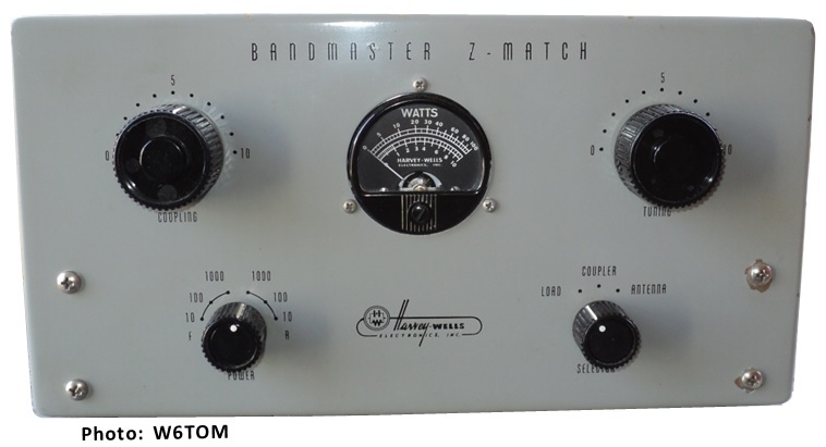
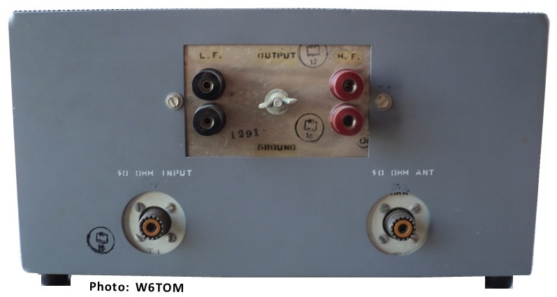
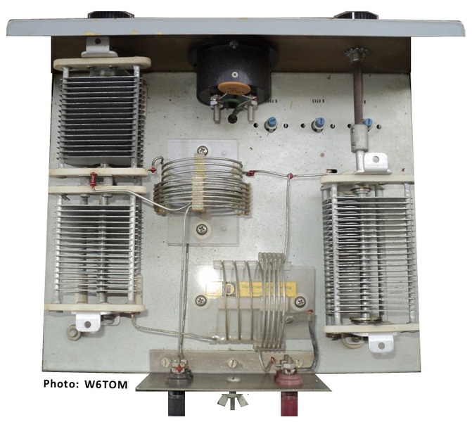
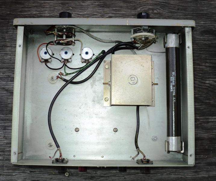
HARVEY WELLS Z-MATCH
This is a beautiful peace of ham radio history. It is a classical Z-Match, meaning it has two sets of tank circuits and two sets of antenna jacks, one for 80/40m and one for 20-10m. 30m usually will work, but which set of antenna terminals you use will depend on the impedance of the antenna.
I only saw one of these once about 50 years ago, and that was here in Germany. I can only speculate on its performance, howerver since it is is a dual-coil Z-match, it is more efficient than the single coil Z-match designs when matching very high or very low impedances.
A great big thanks to Tom, W6TOM for sharing his pictures with us.
* * * * * * * * * * * * * * * * * * * * * * * * * * * * * * * * * * * * * * * * * * * *
.
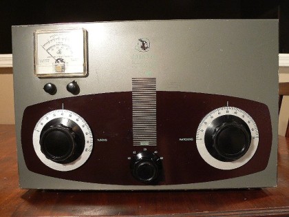
Johnson Viking Kilowatt Matchbox
For many people, this Link-Coupled matchbox is the greatest matchbox ever built; the King of them all.
The fact is, in its day it was supreme but by today standards it falls somewhat short of our needs. Indeed the Annecke Symmetrical Coupler is superior in its matching ability.
In the meantime the J.V. Kilowatt Matchbox has become a collector item. For many people modifying these would be a criminal offense. But if you value performance more than collectors' value, the addition of a switch and a third variable capacitor will give you similar performance to that of the Annecke matchbox.
See: Viking Vs. Annecke for more information on this mod.
Johnson Viking Kilowatt Matchbox Manual.[...]
PDF-Dokument [599.2 KB]
* * * * * * * * * * * * * * * * * * * * * * * * * * * * * * * * * * * * * * * * * * * *
.
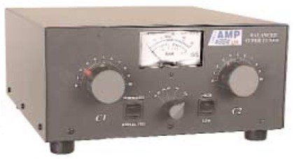
LINEAR AMP UK LA-STWM
(SUPERTUNER)
A truly balanced line ATU. It is inductive coupled which sounds like link coupled, but I idn't see any links around the coils. The reason was simple: the switched coil is on the outside and the link coil is inside the larger coil, hiding the view. I saw inside one of these about 12 years ago and it had nice huge components.
- Matches 20 to 2000 Ohms
- It was rated for 1.5kW
- Series tuned on 10m to 20m
- Parallel tuned on 30m to 160m
Since it uses seperate terminals for 10-20m and 30-160m, it certainly sounds to be a Z-Match.
DOWNLOAD: PRODUCT BROCHURE
This gives a fairly good general description of the matchbox, but it does not specify exactly whether it is link coupled or not.
supertuner.pdf
PDF-Dokument [24.7 KB]
* * * * * * * * * * * * * * * * * * * * * * * * * * * * * * * * * * * * * * * * * * * *
* * * * * * * * * * * * * * * * * * *
HOME-BREW PROJECT
PA0FRI'S S-MATCH
This is just one of several examples of home-brew S-Match matchboxes that you will find on PA0FRI's Web Page.
Very Simple: Just two knobs; a roller inductor and one variable capacitor.
The heart of the S-Match is the special matching transformer in the center of the picture. It is very simple and inexpensive to build.
The S-Match was written up in RSGB's RADCom, but I have not seen the article. I have not seen or heard of any documented tests of this matchbox, I have only read feedback from hams who have built them. All seem to be very happy and I have not heard anything negative about them.
I will build one and then I will know!
Obiously there is no instruction manual, but there is a good web site for those who would like to home-brew their own S-Match: www.pa0fri.com . Once you are on the web site, click on "ATU" in the top menu, and then click on S-Match on the next page.
* * * * * * * * * * * * * * * * * * * * * * * * * * * * * * * * * * * * * * * * * * * *
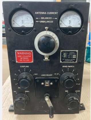
Technical Material Corporation TMC-TAC-1
This is an antenna tuner especially built for use with the military BC-610 transmitter. It replaced the BC-939 Antenna Tuner.
These were used in World War II.

A later version was designed for use with the TMC GPT-750 transmitter.
Of course these antenna tuners could be used with any transmitter having a 50 to 70 Ohm output.
Both versions were designed to match the 70 Ohms output of the TX to a balanced load between 50 and 1200 Ohms.
Its claimed efficiency is 80% between 2 and 18 mcs. Slightly lower efficency in the range of 18 to 30 mcs. (mcs = MHz)
DOWNLOADS:
This version was designed for use with the military BC-610 transmitter.
TMC-TAC-1_BC610.pdf
PDF-Dokument [762.2 KB]
This version was especially designed for use with the Military GPT-750 transmitter.
TMC-TAC-1_GPT750.pdf
PDF-Dokument [5.8 MB]
* * * * * * * * * * * * * * * * * * * * * * * * * * * * * * * * * * * * * * * * * * * *


N E W

A Short Video by W8JI
N E W
OCFD ANTENNA
PRESENTATION


( Info-Only; NO SALES! )
Spiderbeam on Facebook:


BRAND NEW
from Spiderbeam:

Mini "SOTA" Pole
by Rob Sherwood NC0B

(AUF DEUTSCH)


Spiderbeam FG Pole

Photo: Nischal Nethrananda

A fun film about
Ham Radio Outdoors
(not just in Tenerife)
(English & German)


(nearly) Invisible Pole

An Aerial-51
Sponsored Expedition:
INTRODUCING
Special purpose Aerials:

Ultra-Lightweight antennas for expeditions and stealth applications.
+
(other)
---------------------
UPDATES:
|
|
-----------------
LL-TUNER "S-MATCH"
added to my
symmetrical tuner page.
----------------------
PROGRESSING:
LOTS OF NEW CONTENT IN THE SECTION:


Since JAN-2013
*******************