
TUNER BALUNS
In Layman's Terms
Note: this is a non-technical document to help new or non-technical hams understand the situation around the tuner balun. Other documents explain in more technical detail, why that is. Links to these documents are provided at the bottom of this page.
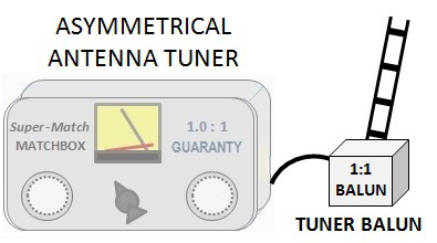
Definition of Tuner Balun: A Balun used in conjunction with an asymmetrical (un-balanced) tuner for the purpose of matching antennas fed with openwire or balunced line feedline.
Golden Rule: ALWAYS use an EXTERNAL 1:1 Current Balun as the Tuner Balun. Do not use a 4:1 balun, regardless of what the impedance is that you are trying to match.
Additionally: If your tuner is unable to match a very high impedance antenna system, and it is not convenient to modify the length of the openwire feedline, it may be necessary to also use a step-up transformer of 1:4. A classical 4:1 balun may be used for this device, but in this case it is only performing the job of a transformer; it is not performing the job of balun. It is inserted between the 1:1 balun and the openwire feedline.
Source of Confusion:
For many years the OEMs (manufacturers) of Antenna Tuners have been equipping their antenna tuners with the wrong type of balun. Many years ago they began using 4:1 voltage (Ruthroff) baluns. Later they changed to 4:1 current (Guanella) baluns. Both of these were wrong, as you will see below.
Worse yet, the Balun OEMs have also recommended voltage baluns, but began recommending 4:1 current baluns when the tuner OEMs changed. Unfortunately you cannot rely on these guys to know what is right. Some are much better informed than others but how do “you” know which ones they are?
NEVER rely on a salesman working at some ham radio shop to know which balun to recommend. His statement will usually begin with “most people buy XYZ”. Well most people have no clue about balun technology and simply buy what everyone else buys.
WHY IS 4:1 WRONG?
In order to understand why that is, we first need to revisit the meaning of the word “Balun” and be reminded of what its purpose really is.
Although most people think a balun is an antenna accessory used for matching a coax transmission line to a balanced antenna, and sometimes even say “to balance the RF current on the antenna” or even sillier, “to balance the antenna”, the balun actually is and accessory for the transmission line, NOT for the antenna.
Consult any ARRL HANDBOOK. You will find baluns described in detail in the chapter on transmission lines – not in the antenna chapter.
In his excellent paper, “Baluns: What They Do and How They Do It”, Roy Lewallen, W7EL described best the purpose of the balun. He also contrasted the Ruthroff (voltage) balun with the Guanella (current) balun in terms of their ability to impede common mode current, and first coined the names “voltage” and “current” baluns. That article initially appeared in the first edition of the ARRL ANTENNA COMPENDIUM, and shortly thereafter, the ham radio community began switching from using voltage baluns to using current baluns with their antennas.
As Roy pointed out, the primary purpose of a balun is to maintain the inherent balance of RF [differential] Current in a feedline. Failure to do this properly can result in Common Mode Current (CMC) on the feedline, causing things to get nasty back in the shack.
A major feature of coaxial transmission line is that the [differential] RF Current, flowing between the TX and the ANT always flows inside of the coax, regardless of what is going on in the outside world around it. Maintaining this balance is important in order to avoid nasty things happening in the shack (e.g., hot mic, hot key, hot chassis, TVI, BCI, equipment randomly going into fault, etc.).
Common Mode Current (CMC) may be caused by many things. One cause, though normally not as bad as we are often led to believe, is feeding a balanced antenna (i.e. dipole) directly with coax and not with a balun. Other more significant causes include running the coax diagonally away from the antenna or running one leg of the antenna over other objects, such as a garage, especially if it has a metal roof.
Another point where CMC can occur is at the junction of an openwire feedline with an unbalanced feedline or device – for instance, where it connects to the asymmetrical antenna tuner. In this case we often have two problems; first the CMC as described above, but also a very high SWR (impedance mismatch), which requires us to take extra steps in dealing with the CMC. This is one of the main reasons the 4:1 balun is not right for the job here.
Funny as it may sound, coax feedline has 3 conductors:
1) inner/center conductor,
2) the inside surface of the shield,
3) the outside surface of the shield.
As stated earlier, the differential RF Current flows inside of the coax, on 1 and 2. It flows to the antenna on one of the wires and returns from the antenna to the transmitter on the other wire. (Remember, it is an alternating current.)
At each and every point along the coax, the magnitude of current in both wires is the same, but opposite in polarity. As such, the current is balanced at that point.
THIS is the balance the balun is supposed to help maintain!
CMC (during transmit) is RF Current that is picked up by the outside surface of the coax; “3)” above. This occurs when radiated RF from one side of the antenna strikes the coax more intensively than radiated RF from the other side of the antenna – for instance when the coax is run diagonally away from the antenna, resulting in it being closer to one side of the antenna than the other.
(Note: there is another type of CMC that occurs during receive, but we’ll discuss that topic for another paper.)
The common mode current flows along the outside of the shield until reaching the SO-239 coax jack at the TX or Antenna Tuner. Here it merges together with the differential current flowing on the inside of the shield, changing the amount of total current on the shield at that point. This in turn disturbs the current balance that was inside the coax, causing an imbalance, and may be the cause of minor or even major problems in the shack or house.
With openwire feedline we may also incur common mode current. It is caused by the same situations that cause common mode current in coax transmission lines.
As stated above, it is especially a problem at the point where the balanced feedline meets the unbalanced 50 Ohm feedline used with our transmitters. This is usually the antenna tuner. Specifically, it is usually the "Tuner Balun" of the antenna tuner.
Common Mode Current must be avoided. It can be reduced, almost completely eliminated by the use of the correct type of balun. Using the wrong type of balun can, under certain circumstances, even increase CMC, rather than impede it.
The ability of a balun to choke or impede the flow of CMC on the line is called its “Common Mode Impedance” or “CMI”.
NOT ALL BALUNS WERE CREATED EQUAL.
Specifically in terms of CMI, which reflects the baluns ability to empede CMC.
ALL BALUNS WERE DEFINITELY NOT CREATED EQUAL.
There are significant differences in different baluns’ ability to impede CMC.
- In general, a 1:1 Guanella Balun (as well as a 1:1 Maxwell Balun) will maintain its CMI value, even in the presence of high SWR.
- In general, a 4:1 Guanella Balun (current balun) has good CMI when it is operating in a perfectly matched condition.
- But as the SWR rises, its CMI falls off rapidly, becoming almost useless once the SWR reaches 5:1 or so.
- NOTE: this can often occur with Tuner Baluns feeding openwire-fed antennas.
- Although the balun continues to transform impedance at a 4:1 ratio, its ability to impede common mode current deminishes significantly, rendering it virtually useless as a balun.
- This is the main reason NOT to use this kind of balun as a tuner balun.
As W7EL pointed out, the 4:1 "voltage" balun is pretty worthless in impeding common mode current and should not be used for this purpose.
Therefore it is imperative to always use a current balun with antennas and to use a 1:1 current balun as the Tuner Balun. If you need additional matching, then the 4:1 Guanella balun may be added as the transformer, but it is doing very little to help with CMI. In this case, you can just as well use a 4:1 voltage balun as the transformer, because it is simpler to build.
One More Reason:
Sometimes the impedance of an antenna is very low at the TX end of the openwire feedline. For example, it might be just 20 Ohms.
- If we use a 1:1 balun, the matchbox sees 20 Ohms which is probably no problem to match.
- If we use a 4:1 balun, the balun is transforming the impedance in the wrong direction and the matchbox sees just 5 Ohms. This may be difficult, even impossible for the matchbox to match.
THEN WHY DOES THE 4:1 BALUN EVEN EXIST?
Simple. Many antennas have an impedance close enough to 200 Ohms for the 4:1 Guanella balun to be effective in impeding CMC. Examples: OCFD, Folded Dipole, and certain types of Loops. The 4:1 current balun works quite well with these.
Buyer Beware: Most balun OEMs are offering a simple, low cost 4:1 Guanella balun based on a single core solution. These baluns do not work; at least they do no perform the full job of a balun because they fail to impede common mode current when used in an antenna. You MUST use a dual-core 4:1 Guanella balun for this purpose.
MAXWELL vs. GUANELLA
The difference is simple; Maxwell is typically a bunch of ferrite beads pushed over the outside of the coax, whereas Guanella is several turns of coax passing through a ferrite toroid. Both have advantages and disadvantages. The Maxwell is easy to build and its CMI is fairly constant over a broad frequency range, but the Guanella has far more CMI than the Maxwell.
WHY “EXTERNAL” TO THE ANTENNA TUNER?
Good Antenna Tuners have a very broad matching range and we use them with all sorts of antennas. Some of us run QRP or just 100w, others run 1kW or more. The amount of CMC and the damage it does depends to a large extent on how much power we are running.
In most cases, a good Maxwell (1:1) balun might suffice. Sometimes a 1:1 Guanella is required. But when the CMC is high and the power level is also high, we will need additional choking (CMI). One way of getting this is to beef up the balun. Add a 2nd, 3rd, or even 4th toroid to the balun. We can easily do this when the balun is external; not so easy when it is internal. See K9YC’s “RFI-Ham” for more on this.
In addition, as Owen Duffy, VK2OD points out; baluns mounted against a metal chassis are subjected to mutual capacitance, which may also disturb the balance. It is simply better to mount them externally in a plastic box. This enables easily beefing the balun up in special cases where you encounter heavy CMC.
MORE INFO:
- Balanced Tuners and common mode current, by VK1OD
- Tuner Balun Ratios: 4:1 or 1:1? , by G3TXQ
- Tuner Baluns, byW8JI
- Choosing the Correct Balun, by W8JI
- RFI-Ham, by K9YC
- Single vs. Dual Core 4:1 Guanella, by DJ0IP

N E W

A Short Video by W8JI
N E W
OCFD ANTENNA
PRESENTATION


( Info-Only; NO SALES! )
Spiderbeam on Facebook:


BRAND NEW
from Spiderbeam:

Mini "SOTA" Pole
by Rob Sherwood NC0B

(AUF DEUTSCH)


Spiderbeam FG Pole

Photo: Nischal Nethrananda

A fun film about
Ham Radio Outdoors
(not just in Tenerife)
(English & German)


(nearly) Invisible Pole

An Aerial-51
Sponsored Expedition:
INTRODUCING
Special purpose Aerials:

Ultra-Lightweight antennas for expeditions and stealth applications.
+
(other)
---------------------
UPDATES:
|
|
-----------------
LL-TUNER "S-MATCH"
added to my
symmetrical tuner page.
----------------------
PROGRESSING:
LOTS OF NEW CONTENT IN THE SECTION:


Since JAN-2013
*******************