
My Favorite 40m "DX" Antenna
NOTE: This is not a plug-n-play antenna. If you want it to work properly, you will need a means of measuring SWR, some trial and error, a little patience and at least half-a-brain to build this.

A 40m Delta Mono-Loop
(Or is it a Mono Delta-Loop? Whatever!)
Click on Drawing -->
Of course I would rather have a full size, 3 element Yagi at 110 ft., but the reality is, I'll never be able to afford that antenna, or the QTH where I could install it.
With age I have learned to couple my dreams with realities. I no longer shoot for the stars. I prefer to shoot for targets I can easily hit.
Most people who want to have a good DX signal on 40m but can't afford a beam, turn to a quarter-wave vertical. Though I often do that too, whenever I can, I put up something better; a 40m delta mono-loop. Granted, if I could lay down 100+ radials, the vertical would probably work just as well, but first of all I'm too lazy to do that and second: the cost.
This antenna is a full wavelength single-delta-loop, with the point of the triangle at the top of the single support pole, and fed near one of the corners - One Quarter Wavelength down the diagonal leg.
Feeding and matching is simple; it's fed with a quarter-wavelength of RG-11 or RG-59 (75 Ohm) coax, and then any length of 50 Ohm coax. No balun is necessary, though an RF-choke is advantageous. The easiest solution here is to slip ferrite beads of high permeability over the coax and secure with heat-shrink tubing.
Advantages over a full size quarterwave vertical with a good radial network:
- 2-dimensional (will fit in a long, narrow space) - radials should normally be in all directions.
- About 1 dB gain, but that's not the real advantage
- Quieter on receive
- More broadbanded resonance than a dipole or vertical
- Yet like a Vertical, pretty much Omni-Directional (due to its low height)
Advantages over a horizontal dipole (at 11m height):
- Lower angle of radiation
- Stronger signal for DX contacts (usually +2 S-Units)
- Local QRM is weaker (usually a few S-Units), thus less QRM
Disadvantages:
- More wire hanging in the air
- More conspicuous to the neighbors
- Not as good as a low dipole for local (NVIS) QSOs (this is an understatement)
I first became aware of this antenna from an article written by DL1BU (SK) in CQDL magazine, April issue, 1979, page 154. I built the antenna immediately and fell in love with it. It is low cost, easy to build and easy to bring into resonance. Note, I use the term "resonance" loosely here. What I actually mean is it is easy to tune the frequency of minimum SWR to anywhere you please, because it is broad-banded so you only have to get close.
I have used this antenna many times in contests and on expeditions, and occasionally I even built one for 80m. I was always pleased with its performance.
Unfortunately I do not have any pictures, so you will just have to look at my drawings.
Why no pictures?
If you get far enough away from it to get the whole antenna into the camera's view finder, you can't see the wire.
DETAILS:
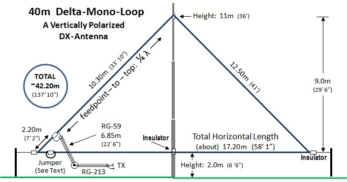
IMPORTANT: DO NOT PLACE TOO MUCH EMPHASIS HERE ON THE OVERALL LENGTH or any other length. REASON: See Sidebar on "LENGTHS" at the bottom of this section.
CONSTRUCTION DETAILS:
TUNING THE ANTENNA:
After installing the antenna, measure the SWR to find the resonance of the antenna and note it. The antenna is probably too long. Adjust length as necessary.
MAKE ALL LENGTH ADJUSTMENTS IN THE HORIZONTAL LEG OF THE ANTENNA.
The antenna is not symmetrical and there is no advantage to trying to shorten or lengthen both diagonal legs. Make the adjustments at the insulator. If you cut the antenna too short, you can just add a loop of wire [JUMPER] and leave it hanging from the insulator. That is usually enough to bring it into resonance on the desired frequency. For home use, the JUMPER is not necessary, but if you are using this portable, you will be adjusting the length a lot and this makes it easy.
SIDEBAR ON "LENGTHS"
I get lots of questions about "lengths" and it’s almost always the same question and always the same answer:
Do NOT place too much focus on the exact lengths shown in the drawing.
I have installed this antenna at several different locations (QTHs), and it was never the same length at any two places. It always had to be adjusted in length to bring the frequency of SWRmin to where I wanted it.
The feedpoint should be:
about ¼ wavelength down either leg from the peak at the top.
This places it slightly up from the corner.
· Exactly how far from the corner DOES NOT MATTER.
- How far
from the top does matter; ¼
wavelength
- (but it must only be “close”, not exact to the inch!)
The height of the pole will play a big role in determining how long the horizontal section must be:
· For HAMs: the higher the better :-)
· For HOAs: the lower the better :-(
Important is that the horizontal section is at least 8 ft. (abt. 2.5m) above ground (at its lowest point), and out of the reach of humans and animals.
This is for safety reasons.
Yes, I know the drawing shows 2m and 6ft., but in the meantime I have met some pretty tall people. Keep it out of their reach!
No, I'm not going to change the drawing!
I made it 15 years ago and can't find the original anymore.
The overall length of the loop is:
· Highly dependent on the height above ground.
· Slightly dependent on the wire type, insulation, etc.
· Slightly dependent on local objects in close proximity of the antenna.
So make the loop slightly longer and prune the length of the horizontal leg to place the frequency of SWRmin wherever you want it in the band.
Remember, the formula for calculating the overall length of the loop (in ft.) is:
L = 1005/f (where f is frequency in MHz).
(BTW: a quarter wavelength is 1/4 of that result)
Notice I inserted an additional insulator in the horizontal leg, near one corner.
This was for two purposes:
1. To enable inserting a loop of wire for tuning purposes.
- This makes it easier if you change locations (QTH) often with the antenna, as I did.
- If you are installing it for permanent use, this is not important.
2. To enable disconnecting the wire, making it one long wire, rather than a loop.
- This makes transportation easier.
- If you are installing it for permanent use, this is not important.
===================================
80 VERSION:
Overall length: 85m
Diagonal length: 25m
Feedpoint: 3m from one of the corners
Horizontal length: 35m
Height at top: 22m
Height above Gnd: 4m
Length of Stub: 13.7m
But, 80m is a big wide band.
Here are some recommendations / estimates of overall length depending on resonant frequency:
- 3520 kHz ca. 85m
- 3700 kHz ca. 81m (diagonals: -1m ; horizontal: -2m)
- 3800 kHz ca. 79m (diagonals: -1.5m ; horizontal: -3m)
I have built the 3520 kHz version twice. I've never built one for higher frequencies within the 80m band. My recommendations for shortening for higher frequencies is a gut feeling, but I don't think "where" you shorten is as critical as just getting the correct length, which has to be found by trial and error anyway.
NOTE: The feedpoint is always One Quarter Wavelength down the diagonal side.
DOWNLOAD INSTRUCTIONS:
80m Loop on 18m Spiderbeam Fiberglass Spiderpole
I just did a quick estimation to see if it might work on this short of a pole. It does fit, but I have not tried it and I cannot say how well it will perform.
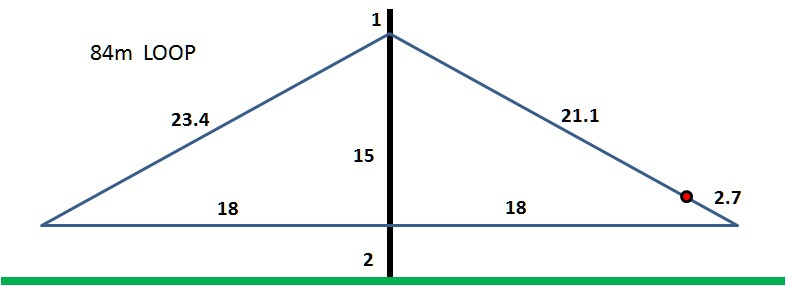
Sketch: DJ0IP
-
2m ground clearance,
-
apex 1m below the top of pole (for stability)
-
84m was "guestimated" as the starting point for the overall size of the loop. Prune in the field for resonance of your choice.
-
Feedpoint was placed 1/4 wl down the pole (note: I did not consider the velocity factor here, but it is not very critical if it is off by a foot or so).
-
Feed with one electrical quarter wavelength of 75 Ohm coax and then extend with 50 Ohm coax.
MY THOUGHTS:
This is a very broad loop (36m wide). It will work for sure and work well, but I have no idea how well it works compared to using the dimensions described above.
THIS HAS NOT YET BEEN TRIED IN THE FIELD.
DO YOUR OWN DUE DILLIGANCE.

N E W

A Short Video by W8JI
N E W
OCFD ANTENNA
PRESENTATION


( Info-Only; NO SALES! )
Spiderbeam on Facebook:


BRAND NEW
from Spiderbeam:

Mini "SOTA" Pole
by Rob Sherwood NC0B

(AUF DEUTSCH)


Spiderbeam FG Pole

Photo: Nischal Nethrananda

A fun film about
Ham Radio Outdoors
(not just in Tenerife)
(English & German)


(nearly) Invisible Pole

An Aerial-51
Sponsored Expedition:
INTRODUCING
Special purpose Aerials:

Ultra-Lightweight antennas for expeditions and stealth applications.
+
(other)
---------------------
UPDATES:
|
|
-----------------
LL-TUNER "S-MATCH"
added to my
symmetrical tuner page.
----------------------
PROGRESSING:
LOTS OF NEW CONTENT IN THE SECTION:


Since JAN-2013
*******************