
Different Kinds of RF-Chokes
COMMON MODE CURRENT CHOKES
You can purchase CMC chokes ready-buillt, or better yet, make one yourself. It's not difficult.
HERE ARE 5 METHODS:
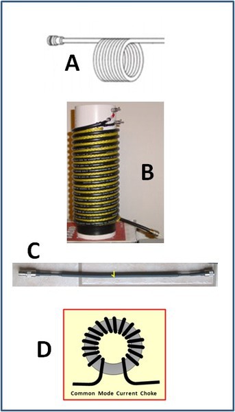
A) COILED COAX CHOKE: Coax wrapped to form a coil. These work, but they are not always good enough. It is the easiest method to try.
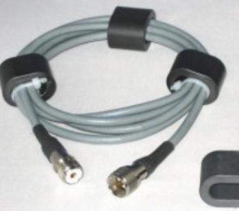
B) IMPROVED COAX CHOKE: Wrap coax onto a PVC pipe, using nylon rope to space the turns. This reduces the mutual coupling and helps keep symmetry in case you are using this as a balun.
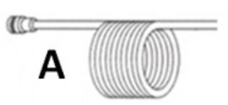
C) FERRITE BEADS OVER COAX: Slide a number of beads over the outside of the coax, and cover with heat-shrink tubing. Then solder the PL connector onto the end of the coax. Tip: using thin Teflon insulated coax enables you to reduce size and weight but still run high power. I usually use one of these just before the coax enters the house. I also use it with commercial
D) COAX WOUND ON A LARGE TOROID: This is also easy to make. I usually use this one for my home-brew wire verticals because it can be built to provision for the radiator, the radials, and even for a series capacitor (if required). I will show this in detail below.
E) COAX LOOPED THROUGH FERRITE CORES
This is the latest method to hit the scene and has
the advantage of being effective, yet low cost.
E
(A) Coiled Coax Choke
The coiled coax choke is the easiest to make but also the least effective. If it works, use it. Otherwise use something better.
For details see the ARRL HANDBOOK or ARRL ANTENNA HANDBOOK.
For impedance details, see the bottom of the chart on Steve Hunt's (G3TXQ) web page on Common Mode Current Chokes: http://www.karinya.net/g3txq/chokes/
Scrambled-Wound Choke? OK or not?
I honestly do not know for sure. I have heard that although it will work, it doesn't work as well as when keeping the turns in a straight row. I have also heard that on 160m it doesn't matter; scrambled is OK. It seems to me you could have unwanted, stray coupling if you scramble the turns.
Until I find out for sure, I will continue to wrap my turns in a straight line as shown in the picture (A) above.
(B) Improved Coaxial Choke
This is a very simple choke to build. The material costs are low, and it is very rugged. You won't burn this one up.
GOOD OR BAD?
You hear success stories with this choke, but you also hear unfavorable reports about them
What is the truth?
The reality is, this is a good method of building a choke but it does not have a broad bandwidth that chokes wrapped on ferrite have. You can't build one and expect it to work from 160 thru 10m. When you build one, you need to decide which bands you want it to cover.
How much impedance must a good choke have?
In most cases, 1K Ohms is enough. If the problem with CMC is not severe, you can usually get by with just 500 Ohms. It is difficult to measure Common Mode Current, but it is not difficult to understand that the more imbalance in your antenna, the more CMC you're going to have. Here are some basic indicators:*
- A symmetrical dipole or beam fed with coax, but without a balun will have a little CMC on the line. Usually 500 Ohms will be enough impedance for these antennas.
- An asymmetrical antenna, such as an Off-Center-Fed dipole (sometimes called "Windom), will have more CMC on the line and needs a better choke (1K Ohm). Note: OCF dipoles are usually fed 1/3 of the way from one end, causing the additional imbalance.
- Some OCF antennas have an even more drametic feedpoint offset, with the feedpoint located just 20% (or less) away from one end. Feeding like this can increase the number of bands the antenna covers, but it also significantly increases the CMC. Here you need about 2K Ohms.
*Any antenna can incur additional imbalances if there are conducting objects in near proximity of one of its sides. In that case you may need more impedance than shown above.
Especially above 7 MHz, if you use more turns than necessary, the chokes performance will degrade. You can get a graphical view of this by studying the chokes at the bottom of the chart on Steve Hunt's (G3TXQ) website. See: http://www.karinya.net/g3txq/chokes/
Here are some general guidlines for winding coax chokes on a 10cm (4 in.) PVC pipe,
using RG-58 for low power or RG-213 for high power:
- 160m: 28 turns
- 80m: 24 turns
- 40m: 14 turns
- 20m: 8 turns
- 15m: 5 turns
- 10m: 4 turns
As stated above, it is best to space the individual windings by about 6mm (1/4 inch) using nylon rope between the windings. For more exact details see the link to G3TXQ's website shown just above the chart.
NOTE: When used with antennas with a lot of Common Mode Current, this "Ugly Balun" is not the best solution. In that case a 1:1 Guanella balun would be far more effective! See "D" (below).
(C) W2DU
(C) Ferrite Beads over Coax
This type of choke is known as the W2DU, or "Maxwell" choke. It is sometimes called a W2DU balun. It is simply a string of ferrite beads over the coax, and then typically covered with heat shrink tubing to keep the beads in place and weather-proofed.
The advantage is, this is very simple to build. The disadvantage is, depending on frequency, you may need a lot of beads. Also, in order to get more than about 500 Ohms impedance on 160m, you need to use a different type of bead from the ones you use for the higher bands. Simple solution. Build two; one for the low bands and one for the high bands, and simply install them in series.
These simple chokes usually solve most "soft" RF problems caused by common mode current, and usually, most of us only have "soft" problems. In cases where the CMC problem is worse, it is better to use another type of choke, such as the Guanella (picutred in "D" above), or the new "Cost Effective Chokes" at the bottom of this page.
GUIDELINES:
Note: Until I update this with guidelines, here are two good sources for these simple chokes.
Choke Kits:
- 80 - 10m: THE WIREMAN Model 8231
- 160 - 10m: THE WIREMAN Model 8232
These cost about $20 and are very simple to build in about 30 minutes.
For $10 more you can buy them already built (8331 and 8332).
In Germany:
- 160 - 10m: DX-WIRE "Wide Band Mantelwellen Sperre"
- 160 - 10m: DX-WIRE "Low Band Mantelwellen Sperre" (better on 160/80m).
Both cost 34 EURO.
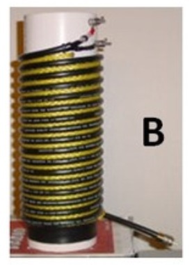
(D) Toroid CMC Chokes . . . (Guanella)
This is a very effective type of CMC choke and very easy to build.
There are two ways to build these:
- Nice and neat in a weatherproof case (see below)
- Quick and dirty; just wrap coax through a large Toroid
- For indoor use, a standard Toroid is fine
- For outside, use a Toroid with a layer of Epoxy on its surface, such as the ones from Ferrocube.
When building a Quick and Dirty, simply wrap the end of your coax around the toroid before soldering the PL-259 onto it. Or, if you wish, you may choose to use a short piece of coax, just long enough to create the number of turns you require, plus short stubs on the ends. Simply solder Coax connectors onto the stubs. This would look like the drawing in "D" above, but with two PLs attached.
TWO CHOICES:
- Dirt-Simple - the coax is wound "continuous" in one direction, like in picture D at the top.
- Simple - the coax is "cross-wound", like in the picture below.
The cross-wound method (Reisert method) reduces mutual capacitance in the windings, thus improving the common mode impedance significantly.
This method was developed by Joe Reisert, W1JR and named after him. This is the method I always use and is certainly the preferred method. Don't worry if you wrap the choke like this, reach the end and find that one side has one more turn than the other; that doesn't matter.
 . . . . . . . . . . CMC Choke wrapped on a Toroid . . . . . . . . . .
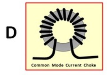
I find it practical to build the CMC choke into a plastic box and include connections for the antenna I will use it for. For instance in the case of a Vertical, I use a box with 5 holes, one for the SO-239 coax jack, and 4 for screws.
- [Top] Screw 1: Top of Choke
- [Top] Screw 2: No Connection. (used when it is necessary to feed the antenna through a capacitor)
- [Side] Screw 3: Radials connection
- [Side] Screw 4: Radials connection
Note: The shield (ground) side of the SO-239 should only connect to the shield of hte coax.
It must not be connected to the radial screws.
All components use for this choke were sourced from Spiderbeam, but this is not a standard Spiderbeam product.
CHOICE OF COAX AND TOROID:
For 160, 80, & 40m, you cannot get enough turns on the toroid using RG-213. RG-58 will work fine, but only for a few hundred watts. For more power, use thin Teflon coax, such as RG-142.
Using RG-142 or RG-58, it is possible to get about 17 or 18 turns onto an FT-240-xx toroid. This is easily enough for 80m and above (but too much for 15, 12, and 10m).
Approximate Impedance on 160m:
- FT-240-61: 500 Ohms
- FT-240-43: 4000 Ohms
- FT-240-31: 4000 Ohms
500 Ohms is just barely enough. Normally it should be enough.
When using a coax connector at the bottom and screws at the top, there is a trick that enables you to keep all of the coil's windings in the same direction, for instance "clockwise", but still exit the box on opposite ends. To do this:
- Begin at the bottom near the coax connector, and wrap half of the turns on one side,
- Then drop the coax back down to the beginning
- and wrap the other half of the turns on the other side, taking care that you continue winding in the same direction (clockwise).
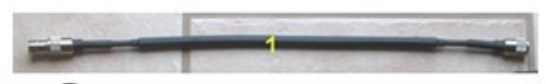
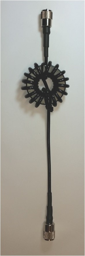
 Pictured is a Spiderbeam 1:1 Guanella balun, 7 turns per side.
When using a coax connector at the bottom and screws at the top, there is a trick that enables you to keep all of the coil's windings in the same direction, for instance "clockwise." To do this:
- Begin at the bottom near the coax connector, and wrap half of the turns on one side,
- Then drop the coax back down to the beginning
- and wrap the other half of the turns onto the other side of the toroid, taking care that you continue winding in the same direction (clockwise).
- The picture on the right shows this method of winding, but keep in mind it has only 7 turns per side. For our low band CMC choke, we need about 8 or 9 turns per side.
- TIP: wrap the turns as tight and close together as you can. Use wire-ties to hold the ends in place.
NOTE: The picture on the right is NOT a picture of the CMC choke. It is a picture of the Spiderbeam Guanella Balun for 40 thru 10m. It is wired differently on top than the CMC choke. The CMC choke I describe here has more turns if it is to lower bands. My CMC choke (like this) is installed in the field, in the middle of a patch of stinger weeds, so I am unable to make pictures.
IMPORTANT: The CMC choke uses the same "winding method" as the balun. So just look at the winding method, NOT the wiring on top. Wire the top according to the drawing above labeled "Common Mode Current Choke," or below under "D2".
HOW MANY TURNS?
Again I recommend using the data in Steve Hunt's (G3TXQ) chart on CMC Chokes.
See: http://www.karinya.net/g3txq/chokes/
For this choke, use the top half of his chart.
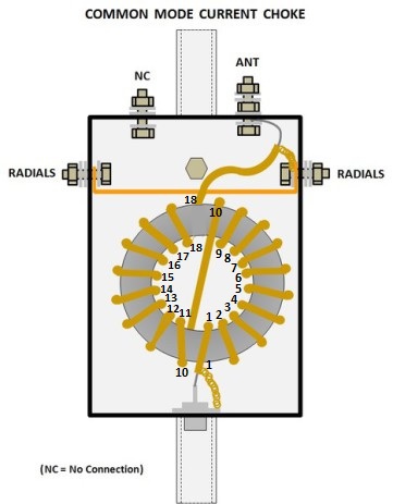
My Choke:
The antenna whose feedpoint is pictured above is an extended 160m Inverted-L, intentionally longer than a quarter wavelength. As such, it is brought into resonance with help of a series capacitor (the blue capacitors soldered in paralell on top of the box). This raises the feedpoint impedance from about 25 Ohms up to 50 Ohms.
The top of the choke is connected to the top right screw. The vertical wire connects to the top left screw, which has no connection inside the box. Thus the antenna feeds through the capacitor.
At this QTH, I only had room for one single elevated radial. It connects to the screw on the right side. The screw on the left has nothing connected to it.
It is important that the ground side of the SO-239 coax connector on the bottom of the box has no internal connection to the two radial screws.
Most vertical antennas don't require a series capacitor. In that case the vertical wire will connect directly to the screw on the top right, and the top left screw is left free.
(D2): 1:1 Guanella (W1JR) Choke Balun
This choke balun consists of :
- 1.40m (4'7") of special Teflon-like Coax (DXW142), similar to RG-142
- with 17 turns cross-wound (W1JR)
- onto an Amidon FT-240-43 or FT-240-31 toroid core.*
- 2x PL-259 with gold-plated contacts and Teflon insulation.
* for 80 thru 10m, use "-43";
* for low bands (160/80/40) use "-31".
DXW142 FEP/TPE-U coax cable 50 Ω Specs:
- Inner conductor material : solid copper, tinned
- Inner conductor diameter: 0.98 mm
- Dielectric: FEP, 3.02 mm
- Power handling (estimated) : 4KW @ 10MHz ; 2KW @ 30MHz
The inner conductor is made of solid copper (with better thermal conductivity than the Copperweld steel wire in RG142B/U). By tinning, FEP was used as a dielectric, since only silver plated wires can be extruded with PTFE. FEP nearly reaches the properties of PTFE
According to the chart on G3TXQ's web page, this
balun (wound on a #43 core) exhibits the following CMI characteristics:
- 160m >4 kOhm
- 80m 8 kOhm
- 40m 4 kOhm
- 30/20/17m 2 kOhm
- 15/12/10m >1 kOhm
For more exact details on core type and number of turns, see the colorful chart on G3TXQ's web site, here: http://www.karinya.net/g3txq/chokes/
(E) Cost Effective Chokes
 Cost Effective Chokes, by GM3SEK
(Modern Ugly Chokes)
Ferrite purchased in small quantities is very expensive. In severe cases of common mode current, the solutions presented above may be inadequate, unless you choose Method D and use several (expensive) toroids.
The concept shown here was first introduced by George Cutsogeorge, W2VJN in the 2010 issue of the ARRL Handbook.
Ian White, GM3SEK designed the 3 chokes pictured here, using common low cost ferrite cores. Left: Low-Band; Right: Mid-Range & Low-Band.
These chokes have high CMI (over 4 k-Ohms), [but only] across a limited frequency specturm. Therefore it takes 3 different chokes to cover the entire HF spectrum. You can use them independently of each other to cover specific ranges, or all three in series to cover 160 thru 10m.
I was unable to find these cores here in Germany so I ordered several dozen from the UK. In the meantime I have built and tested these chokes and found them to be an excellent compromise between effectiveness and cost. Their ability to impede CMC rivals that of the Guanella (type D above), but these are cheaper.
I will update this space after I have done more testing.
In the meantime you can click on the picture for more information.

N E W

A Short Video by W8JI
N E W
OCFD ANTENNA
PRESENTATION


( Info-Only; NO SALES! )
Spiderbeam on Facebook:


BRAND NEW
from Spiderbeam:

Mini "SOTA" Pole
by Rob Sherwood NC0B

(AUF DEUTSCH)


Spiderbeam FG Pole

Photo: Nischal Nethrananda

A fun film about
Ham Radio Outdoors
(not just in Tenerife)
(English & German)


(nearly) Invisible Pole

An Aerial-51
Sponsored Expedition:
INTRODUCING
Special purpose Aerials:

Ultra-Lightweight antennas for expeditions and stealth applications.
+
(other)
---------------------
UPDATES:
|
|
-----------------
LL-TUNER "S-MATCH"
added to my
symmetrical tuner page.
----------------------
PROGRESSING:
LOTS OF NEW CONTENT IN THE SECTION:


Since JAN-2013
*******************