
Off Center Fed (OCF) Dipole Antennas
( W I N D O M )
The most difficult subjects can be explained to the most slow-
witted man if he has not formed any idea of them already; but
the simplest thing cannot be made clear to the most intelligent man if he is firmly persuaded that he knows already, without a shadow of a doubt, what is laid before him...Leo Telstoy, 1897.
THIS IS THE MAIN PROBLEM FACING THE WINDOM/OCFD !
(DJ0IP, 2018)
Indeed, the biggest challenge we have in understanding these antennas is disregarding what we thought we already knew about them.
Although "OCF" is the more accurate term for these antennas,
I like the name "WINDOM" much better
and use it enterchangably throughout my writings on OCF antennas.
WHAT IS AN OFF-CENTER-FED DIPOLE ?
.
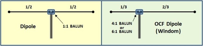
Whereas a Dipole is a half-wavelength long radiator, fed in the Center of two equal length legs, the Off-Center-Fed Dipole (which I prefer to call a WINDOM) is a Dipole whose feedpoint is at a point removed from the center of the antenna.
The picture above on the left shows the classical Dipole, which is usually fed with 50 Ohm coax, through a 1:1 balun.
The picture on the right above shows an OCF Dipole with the feedpoint positioned at the same feedpint of the classical WINDOM antenna, fed with 50 Ohm coax through a 4:1 or 6:1 balun at a point 1/3 of the distance from one end.
Note: It is not imperative to feed the OCF antenna at the point shown. It is sometimes advantageous to choose a different point to feed it. Changing the location of the feedpoint will SIGNIFICANTLY change the characteristics of this antenna.
Why OCF?
The simple answer is: to be able to work more bands with one antenna.
A dipole is basically a mono-band antenna. It is sometimes used on its 3rd harmonic (i.e., a 40m dipole may also be used on 15m), but if it is fed with coax, it should not be used on its even harmonic frequencies. That's because the impedance of the dipole on its even harmonics is too high (typically >2K Ohms) and feedline losses are excessively high.
By moving the feedpoint away from the center of the dipole,
we enable the antenna to be used on more harmonic frequencies.
We transform the mono-band antenna into a good multi-band antenna.
THE COST: You will need to use a 4:1 or 6:1 balun.
CAUTION: THIS IS NOT AN "ALL-BAND" ANTENNA, IT IS A "MULTI-BAND" ANTENNA.
In the past, I was a big fan of openwire fed antennas. Indeed, I used these for nearly 50 years, any time I wanted a single wire antenna to cover multiple bands.
I recently switched my multi-band antenna preference
from openwire-fed/center-fed dipoles to coax-fed OCF dipoles.
Some will argue that the 'openwire-fed/center-fed' dipole is the most efficient antenna there is, when you are looking to cover 5, 6, 7, or even more bands with just one wire antenna. I don't dispute this point. However I do challenge the openwire-fed dipole's "perceived" postion of being the "best" solution no matter what. I suggest we consider the following:
- “How much more efficient is it than other alternatives?"
- “What disadvantages does it have ?”
- "For short feedline lengths, other solutions are more practical."
Openwire-Fed Dipoles REQUIRE a matchbox - on all bands, all the time.
AND that is their BIGGEST disadvantage. But it doesn't stop there . . .
In fact, the best way to match them is with a fully symmetrical matchbox, not just any old matchbox. These matchboxes are rare and very expensive compared to the more common asymmetrical matchboxes. It has taken me many years to realize that this method is not the only way to efficiently achieve multi-band performance. I have finally woken up!
INSTEAD of feeding the dipole in the middle with openwire, let's consider feeding it off-center with coax, through a 4:1 balun. It certainly works! But what is the downside?
The downside is slightly higher losses.
HOWEVER, AS LONG AS THE FEEDLINE IS LESS THAN 100 FEET LONG, the difference remains LESS THAN 1 dB* “if” you build it right.
*Reality Check: Most people using openwire feedline today are not using the correct type of matchbox and as a result, incurr MORE LOSS IN THEIR MATCHBOX than the loss incurred when using an OCF instead of an openwire-fed dipole.
Done right, the performance and efficiency of the OCF approaches that
of the 'openwire-fed/center-fed dipole', without all the disadvantages.
So what can be done wrong with an OCF?
- Wrong type or poor quality of balun.
- Cheap, poor quality coax with excessive loss
- Wrong choice of design, and then compensating with a matchbox.
- THIS is the most common thing people do wrong.
The problem with openwire-fed/center-fed antennas like the double-zepp is, antennas resonant on one band have a ridiculously high impedance on their 2nd harmonic. It is no different than a normal dipole, as described above. It can be difficult, sometimes even impossible to match the 2nd harmonic band without having to change the feedline length, unless you use monster matchboxes.
BTW, "monster matchboxes",
especially those capable of handling high power,
are very E-X-P-E-N-S-I-V-E !
Despite this fact, I owned and used monster matchboxes for many years and was completely satisfied . . . but I spent a lot of money on matchboxes !!!
Now that I am retired, I am no longer able to throw bundles of cash towards matchbox purchases. I have taken a more pragmatic look at the realities. Today the OCF is much more appealing to me than an openwire-fed dipole.
WHAT ABOUT PORTABLE OPERATIONS?
I have always been a great fan of portable operations, and when working portable, it is preferable to use antennas which require no matchbox at all, or if one is required, then it should suffice to use something tiny and low-cost.
I found this to be impossible with the traditional openwire-fed dipole.
I studied the impedance variance of dipoles as a relation of their feedpoint position and noticed that you don’t have to move too far away from a worst case scenario to achieve a much more match-friendly impedance on most of the bands. I then sat about to find a combination of length and feedpoint position that enabled me to present a “civilized load” to the transceiver.
"Civilized" meaning here that the antenna has close to 50 Ohms, or at least
that it can be matched efficiently by a low-cost asymmetrical matchbox.
I have used Ten-Tec transceivers for my home station for most of my 50 years on the air, because they have no problem to deliver full power, 100w all day long into a 3:1 SWR.
Many Japanese transceivers don’t like this and fold back their output power in the presence of even moderate levels of SWR. These tranceiver require a matchbox when others do not.
PEOPLE SHOULD ALSO CONSIDER THIS DOWNSIDE
WHEN MAKING TRANSCEIVER PURCHASING DECISIONS.
I have also used JA transceivers with built-in ATUs that could match at least 5:1. This, together with an OCF has enabled me to work many bands without the need for an expensive symmetrical matchbox.
BUT IT MUST BE AN OCF WITH A GOOD DESIGN, NOT JUST ANY OCF!
Many hours of computer modeling were followed by 10x as many hours in the field, measuring, and then evaluating the OCF antenna results on my computer. Nothing seemed to work like I wanted it to.
I was almost ready to give up, when I got the idea to replace my MFJ-259B analyzer with a RigExpert AA-54 analyzer. The AA-54 can scan the entire HF spectrum within a few seconds, thus saving me loads of time spent taking multiple manual measurements on each band.
After I became familiar with this new analyzer, I quickly came to a conclusion with my 7-band 80m OCF and soon afterwards developed a 5-band 40m OCF. Voila!
If your are serious about playing with the design of the OCF antenna on your own, do yourself a favor and invest in a good antenna analyzer which can scan the HF spectrum.
I now have two OCF antennas in operation:
I generally do not need to use a matchbox on any band; EXCEPTION: 80m of course.
I don't need a matchbox in the CW portion of the band - only when working in the higher SSB portionof the band. No dipole ever covers the entire 80m band without the use of a matchbox, unless you build something very exotic such as cage dipoles, etc.

N E W
OCFD ANTENNA
PRESENTATION


( Info-Only; NO SALES! )
Spiderbeam on Facebook:


BRAND NEW
from Spiderbeam:

Mini "SOTA" Pole
by Rob Sherwood NC0B

(AUF DEUTSCH)


Spiderbeam FG Pole

Photo: Nischal Nethrananda

A fun film about
Ham Radio Outdoors
(not just in Tenerife)
(English & German)


(nearly) Invisible Pole

An Aerial-51
Sponsored Expedition:
INTRODUCING
Special purpose Aerials:

Ultra-Lightweight antennas for expeditions and stealth applications.
+
(other)
---------------------
UPDATES:
|
|
-----------------
LL-TUNER "S-MATCH"
added to my
symmetrical tuner page.
----------------------
PROGRESSING:
LOTS OF NEW CONTENT IN THE SECTION:


Since JAN-2013
*******************