
DOES THE CAROLINA WINDOM WORK ?
[ The CW ]
I didn't know either, but I wanted to find out.
Many people hold endless debates in forums, model until the cows come home and debate some more on this topic. If that's what turns you on, great! It doesn't work for me.
I use a different approach. I buy (or build) the antenna in question and compare it to whatever other antennas I happen to have installed at the time, as well as compare it [subjectively] to my 50 years experience playing with antennas in DX contests; even winning some and setting a few all-time high score country records.
What works for me, works for me, but may not work for you!
DO YOUR OWN DUE DILLIGENCE.
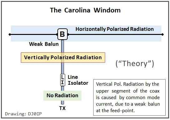
First, a look at the theory behind the Carolina Windom concept:
HERE IS WHAT I FOUND OUT
after 2 years of extensive testing
of 3 different models of Carolina Windoms:
I found the CW to be a good dipole, nothing more, nothing less.
I could not find any improvement in performance over a standard OCFD. However I did find the antennas to be the heaviest wire antennas I had ever used and they were not cheap.
Common Mode Current in OCFD Antennas:
In the summer of 2013, I conducted a field test of Common Mode Current on 40m OCFD antennas (see: CMC Test), with the goal of understanding how CMC affects the antenna, how lengths of feedline affect the CMC, and how efficient different balun and choke designs are at impeding CMC.
I spent the winter of 2012/2013 planning and preparing for the test, with the help of Steve Hunt, G3TXQ (SK) and David Cutter G3UNA. This included building all of the chokes and baluns I would need for the test, as well as calibrating test equipment as per the advice of Ian White, GM3SEK.
The test involved about 10 hours per day, 7 days per week, for 3 weeks. Part of the day was spent in the field putting up antennas and measuring, and part was spent on the computer, recording and evaluating results, and then creating graphs showing the results.
One of the things I was looking for was how the presence of CMC affects the shape and magnitude of the SWR curves across each of the bands, 40, 20, 15, 10m.
I made about 1000 measurements altogether. Half were CMC measurements with 100 Watts applied to the antenna, recording the results in mA, the other half were individual band scans of the SWR across each band, which showed both the magnitude of the SWR and the shape of the SWR curve. Thus, for each graph, I had an associated CMC measurement.
CMC clearly distorts things!
What I found was that the amount of CMC on the fundamental (40m in this case) was a magnitude greater than it was on any of the higher even harmonic bands. CMC was higher on the 3rd harmonic (15m) than on the even harmonic bands, but not as high as on the fundamental.
My first (false) explanation was that this was due to the electrical height of the antenna above ground. Tom Rauch (W8JI) assured me that CMC has nothing to do with height. I accepted that because Tom is usually always right.
So what was the explanation for this?
In a recent discussion on OCFD in a FB antenna group, Tom explained:
Rick Westerman The common mode is caused by the impedance and voltages at the feed more so than the asymmetry. It is harder to settle down a 200 ohm feedpoint than a 50 ohms feed point because the voltage is higher.
If you feed an OCF through a modest or low common mode impedance balun with a coaxial feedline, there is only a minor difference when the center side and the shield side are reversed. Perhaps 20-30%.
The higher feed impedance by moving off center increases feed voltage at any given power, and that is what mostly causes increased common mode.
It would be an understatement to say that a light went on . . .
It was more like a flood lamp!
At the center of a half-wave dipole, the current is maximum and the voltage is minimum.
Thus, from a CMC standpoint, this is the best place to feed a halfwave wire antenna.
As we move the feedpoint away from the center, current decreases and voltage increases.
As the voltage increases, the CMC increases. From a CMC standpoint, the ends of the wire are the worst place to feed it.
Even harmonics invert characteristics; i.e., 20 and 10m have low current and high voltage at the center of a 40m dipole; odd harmonics repeat; 15m has high current and low voltage. However, due to the different effect that end effect has on the higher bands, the 15m curves skews slightly resulting a shift in current max. and voltage min. away from that of the fundamental's. This explains why, when fed off-center, the CMC was higher on 15m than on the even harmonic bands, though not as high as on the fundamental. In fact, I found the level of CMC on the higher even harmonic bands to be trivial; alomst unmeasurable.
Applying this to the Carolina Windom:
Since the verticaly polarized feedline radiation is only possible when CMC is present on the feedline, there will be no significant vertically polarized radiation on higher even-harmonic bands, because there is almost no CMC. Also, the amount of CMC I measured on 15m was significantly lower than on 40m. Thus the amount of vertically polarized radiation on 15m is very low.
But how much difference does it make in real life, on the bands, on the fundamental band?
Unfortunatley, finding this out cannot easily be measured with instruments, and relying on QSO experience is not very scientific. A direct A/B comparison is very difficult due to space requirements when erecting both antennas at the same time. What I could do is A/B comparisons with a third antenna, located physically far enough away as to not interact with the antenna.
Also, 50 years of active DX contest partcipation, making between 500 and 1300 QSOs per contest weekend helps one understand how well different antennas work. My interpretation and conclusion follows below. This is not scientific, but better than a short term A/B test between two antenna.
I was seriously hoping these antennas would give me the DX benefit "claimed" in their advertisement. I wanted them to work. I was not trying to prove that they do not work.
To ensure I was giving these antennas every chance, I invested (and wasted) a lot of money on an expensive thick-wall fiberglass pole to host the CW antennas. For best results, your pole or mast should not be of metal.
After I completed the tests, I replaced this with an aluminum mast and went back to a standard, home-brew double-dipole for 80/40m. At some QTHs I used a normal 80m OCFD antenna, albeit not with the 1/2 - 2/3 feedpoint; that won't work on 15m. I use other feedpoints in my OCFD's.
Perhaps someone out there will find some application which benefits from the characteristics of the Carolina Windom. I couldn't find one.
My OPINION:
The entire CW concept is Snake Oil, adding unnecessary complexity and weight to the OCFD.
You will have far better DX results by building your OCFD as lightweight as possible, feeding it with lightweight coax (i.e., M&P Airborne-5 or Airborne-7), then raising it higher into the air than you can get the heavy Carolina Windom.
HEIGHT = MIGHT Tricks and Gimmicks won't compensate for a low antenna.
For now, you can read my story in the PDF download below.
A document describing my personal experience with 3 different models of Carolina Windoms, over 2 years of testing.
Does the Carolina Windom Work.pdf
PDF-Dokument [287.7 KB]


N E W

A Short Video by W8JI
N E W
OCFD ANTENNA
PRESENTATION


( Info-Only; NO SALES! )
Spiderbeam on Facebook:


BRAND NEW
from Spiderbeam:

Mini "SOTA" Pole
by Rob Sherwood NC0B

(AUF DEUTSCH)


Spiderbeam FG Pole

Photo: Nischal Nethrananda

A fun film about
Ham Radio Outdoors
(not just in Tenerife)
(English & German)


(nearly) Invisible Pole

An Aerial-51
Sponsored Expedition:
INTRODUCING
Special purpose Aerials:

Ultra-Lightweight antennas for expeditions and stealth applications.
+
(other)
---------------------
UPDATES:
|
|
-----------------
LL-TUNER "S-MATCH"
added to my
symmetrical tuner page.
----------------------
PROGRESSING:
LOTS OF NEW CONTENT IN THE SECTION:


Since JAN-2013
*******************