
THE OCF (WINDOM'S) DEVIL'S TRIANGLE
Although "OCF" is the more accurate term for these antennas, I like the name "WINDOM" much better and use it interchangably throughout my writings on the OCF antennas.
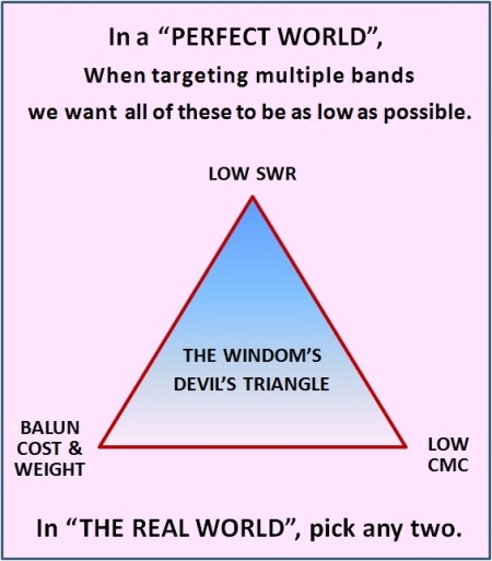 . . . . Note: "CMC" = Common Mode Current
.
OLD (OUT-DATED) ASSUMPTION:
WITHOUT AN ANTENNA TUNER:
- AN 80M OCF WORKS ON JUST 4 BANDS: 80/40/20/10m
- A 40M OCF WORKS ON JUST 3 BANDS: 40/20/10m
"MULTI-BAND" is one of the Windom's (OCF's) biggest attractions.
In our quest to squeeze more bands out of our multi-band Windom,
we often run into several problems:
- Poor Efficiency
- Narrow Bandwidth on one or more bands
- Commn Mode Current (CMC) Problems
BEWARE OF MARKETING CLAIMS REQUIRING A MATCHBOX/ANTNENNA TUNER.
Some OCF antenna manufacturers claim their antennas will match a greater number of bands than other OCF antennas. In the fine print you will read "requires a matchbox".
Although the classical OCF antennas can be "bent" to show a good match when tuned with an antenna tuner, there are two huge disadvantages in doing this:
- You will have significant loss in the coax and balun*
- The balun may possibly burn up and require replacing
*Typically a minimum of 10% loss, often as much as 50% or more loss!
The Trick for Covering More Bands: "Move the Feedpoint"
The classical Windom (OCF) places the feedpoint 1/3 of the way from one end (2/3 of the way from the other end).
By moving the feedpoint to a different location, we are easily able to obtain more bands from our Windom.
- 80m OCF: 80/40/30/20/15/12/10m*
- 40m OCF: 40/20/15/10m*
*possibly 6m
Potential Problems when Moving the Feedpoint:
- The SWR on some bands may be a little worse than with the classical feedpoint
- The Bandwidth may be smaller on some bands
- You may potentially incur problems (sometimes significant problems) with Common Mode Current (CMC).
The Problems caused by Common Mode Current:
CMC can cause several unwanted side effects to our operations:
- Distortion of SWR measurements
- RF in the Shack... appearing as a mic or key being "hot"
- EMI interference in the house (e.g., TVI or RFI, etc.)
- Unwanted noise level when receiving, due to picking up RFI from consumer products in the household
CMC is often found on transmissions lines. It can be caused by feeding a balanced antenna (i.e., Dipole) with an unbalanced transmission line (i.e., coax), or by running the transmission line closer to one side of the balanced antenna than the other. In the case of the coax-fed dipole, a good balun will usually cure the problem. Sometimes additional steps are necessary.
By definition, the Windom is not a balanced antenna
and CMC is always present at the feedpoint.
But some Windoms have much more CMC problems than others.
This is primarily a factor of "where" we place the feedpoint, and how we run the coax away from the antenna.
When trying to get the best SWR on as many bands as possible, a feedpoint is usually chosen which is very lopsided, for example:
- 80m: just 20% from one of the ends.
- 40m: just 17.4$ from one of the ends
In my multitude of tests with the Windom antenna, I have concluded that the farther away the feedpoint is from the center of the antenna, the bigger the problem is with CMC.
Never-the-less, the CMC problem may usually be kept under control by using sufficient "hardware" at the feedpoint. We do this by using a better quality of balun and if necessary, adding a second, 1:1 current balun, also referred to as an RF-Choke or CMC Choke.
Unfortunately, dealing with CMC problems like this adds considerably more weight, wind load, and cost to the antenna. Additional weight can cause excessive sag in the antenna when span as a flat-top, or can break the thin upper segments of a lightweight fiberglass telescoping pole when hung as an Inverted-V on this type of pole.
THUS THE TERM, "DEVIL'S TRIANGLE":
Moving the feedpoint to improve SWR, increases the CMC. If you address the CMC problem, then you add weight and complexity. Seems we can't have our cake and eat it too.
THE SOLUTION: Accept a Reasonable Compromise
TYPICAL COMPROMISES:
- Fewer Bands
- Slightly Higher SWR on some of the bands
- Use a heavier duty pole and a more complex (expensive) balun/CMC-Choke
DO NOT COMPROMISE ON CMC!
CMC IS ALWAYS A BAD THING AND SHOULD BE ELIMINATED!
DECISION TIME:
When beginning a new antenna project with the goal of building your own Windom antenna,
you MUST define EXACTLY what you want the antenna to do:
- Which bands must it cover?
- What are the acceptable SWR maximums it can have?
- What kind of support (mast or pole) are you going to use?
- How much money are you willing to spend?
- Are you prepared to use an antenna tuner on some of the bands?
BE HONEST WITH YOURSELF.
Answers like "SWR as low as possible" and "cost as low as possible" are worthless answers. You are failing to do your homework if that's the best answer you can come up with.
Find out the SWR limitations of your transceiver.
- What is the maximum SWR it can cope with without being damaged?
- If it has fold-back protection (and most Japanese transceivers have this*), at what SWR level does the power begin to fold back? How much does it fold back when the SWR is 1.5:1? 2:1? 2.5:1?
*There are many transceivers on the market which deliver full output power (100w) into a 3:1 SWR without damage to the transceiver. For instance almost all Ten-Tec transceivers can do this. When choosing a new transceiver, don't just look at "how much power" the transceiver can run; also look at what SWR limits it has before it begins folding back power. MOST transceivers have a built in ATU, so this is not a big issue...except, some transceivers have a highly limited matching range (i.e., only 3:1), so buyer beware!
CONCLUSIONS:
- There is not going to be one design which will meet all requirements.
- Which design we choose will depend on what we want the antenna to do.
- The design we choose for home use may be completely different than the design we choose for portable use.
It's Horses for Courses again!
AND remember, when we start moving the feedpoint away from the clasical position (33.3/66.7), the sweet spot we are trying to find (exact position of the new feedpoint) is often very narrow. It's position is influenced slightly by things like height of the feedpoint and heights of the two ends, angle of the legs (in case of Inverted-V) and type of ground underneath the antenna. Of course it may also be influenced by surrounding objects.
THEREFORE you should not expect to be able to take somebody else's antenna results, build the exact same antenna and have it work exactly like his. You may need to move the feedpoint a centimeter or two in one direction or the other.
An antenna analyzer is a very useful tool when experimenting with Off-Center-Fed Dipoles - especially an analyzer that can scan entire bands at one time (example: RigExpert AA-54). These make the work 100x easier than trying to take measurements one at a time with an SWR bridge.


N E W
OCFD ANTENNA
PRESENTATION


( Info-Only; NO SALES! )
Spiderbeam on Facebook:


BRAND NEW
from Spiderbeam:

Mini "SOTA" Pole
by Rob Sherwood NC0B

(AUF DEUTSCH)


Spiderbeam FG Pole

Photo: Nischal Nethrananda

A fun film about
Ham Radio Outdoors
(not just in Tenerife)
(English & German)


(nearly) Invisible Pole

An Aerial-51
Sponsored Expedition:
INTRODUCING
Special purpose Aerials:

Ultra-Lightweight antennas for expeditions and stealth applications.
+
(other)
---------------------
UPDATES:
|
|
-----------------
LL-TUNER "S-MATCH"
added to my
symmetrical tuner page.
----------------------
PROGRESSING:
LOTS OF NEW CONTENT IN THE SECTION:


Since JAN-2013
*******************