
RF CURRENT FLOW
First let's take a look at RF Voltage and RF Current flow on a half wave (resonant) piece of wire for 80m. Although for the purpose of designing a multi-band antenna, we will focus on just the RF current distribution, it's helpful to begin by understanding the voltage and current relationship with each other.
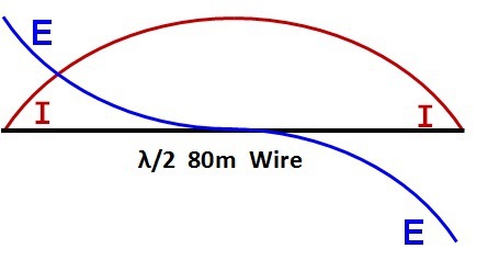
FIGURE 1:
Voltage and Current Flow
- The wire is resonant half wavelength on 80.
- Voltage is maximum on both ends and zero (in theory) in the middle of the wire.
- Current is maximum in the middle of the wire and zero (in theory) on both ends.
Other Important Facts:
- Maximum RF radiation occurs at the point of maximum RF current.
- Minimum RF radiation occurs at the point of minimum RF current
- In free space, the impedance in the middle (max. I) is about 72 Ohms
- In free space, the impedance at each end (min. I) is infinity. BTW, on mother earth it is typically about 2500 Ohms, but varies with height and charachteristics of the earth underneath it.
- On Earth (!), the impednce along the wire varies (typically) between 72 Ohms and 2500 Ohms.
Radiation Pattern:
- The radiation pattern is always the same, regardless of the position along the wire we feed it at.
- At its fundamental frequency it has two major lobes, resembling a figure 8, broadside to the plane of the wire.
Radiation Efficiency:
- The radiation efficiency is dependant on the efficiency of the match to the transmission line, and is independent of the feed point position along the wire.
- It can be argued that it is easier to feed it in the middle with 75 Ohm coax, then we don't have to worry about matching it. Fair enough. But that has limitations too (i.e. makes it a monoband antenna, with fair performance on its 3rd harmonic).
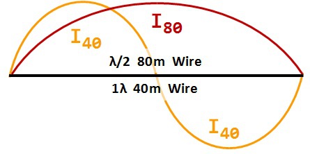
FIGURE 2:
RF Current Flow on 80 & 40m
Our half wl of wire on 80m is a full wl on 40m, which means RF on 40m will complete a full cycle (360 degrees).
Of course one half cycle coincides with the current flow on 80m, but the second half cycle is of opposite polarity.
THIS MAKE ABSOLUTELY NO DIFFERENCE!
BOTH HALVES RADIATE EQUALLY STRONG!
Observe the point at which the 40m current crosses the 80m current:
it is 33.3% of the length of the wire
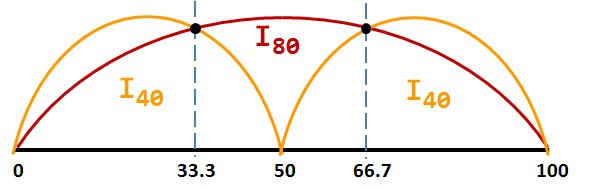
FIGURE 3:
Practical Representation
of RF Current Flow
Since the sign (+ or -) of the current makes no difference to the magnitude of the RF current radiated at that point of the antenna, we may also use the absolute value of both half cycles and represent them as shown here.
Now we see that the two curves cross each other twice, at the 1/3 and 2/3 mark.
Assuming we are running the same amount of power on both bands, since the current is the same, the resistance must be the same. In free space it is; here on mother earth there is a slight difference, due to the difference in the way "End Effect" affects each band. It is just a tiny difference but it is important to realize that it exists.
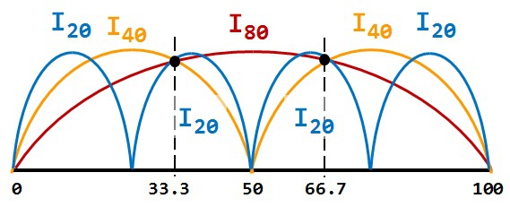
FIGURE 4:
RF CURRENT FLOW, 20m
No surprise here; the 20m RF curve also passes through the same two points. The tiny difference shown here is due to my inability to draw accurately. (sorry).
Again, the difference in the affects of End Effect causes the current curve to shift slightly but the difference in not great.
Guess what happens when we bring 10m in?
Right, it has 8 peaks and also crosses the same two points.
Therefore if we feed at either the 1/3 or the 2/3 mark, the impedance in free space will be the same on all 4 of these bands and down here on mother earth it is close enough for government work!
THE NEXT QUESTION: WHAT DOES 15m LOOK LIKE?

FIGURE 5:
15m Current Distribution
Keepin with the pattern:
- 80m: 1 Peak
- 40m: 2 Peaks
- 20m: 4 Peaks
- 15m: 6 Peaks
15m shown here in green.
OBSERVE THE 33.3% and 66.7% MARKS.
15m RF Current = ZERO
According to Ohm's Law, R = E / I . . . so if I = 0, the R = Infinity. In free space this would be true.
Here on mother earth it is usually about 2K to 2.5K Ohms.
AND more important, because of the affeckt of Skin Effect, which skews the upper harmoinc bands slightly, 15m is actually a few percentage points away from the 0 current point at the 33.3% mark on the wire.
Therefore we do get some 15m radiation at this point, but not much compared to the other bands.
However the SWR is ridiulously high on 15m band when using the 1/3-2/3 feedpoint.

N E W
OCFD ANTENNA
PRESENTATION


( Info-Only; NO SALES! )
Spiderbeam on Facebook:


BRAND NEW
from Spiderbeam:

Mini "SOTA" Pole
by Rob Sherwood NC0B

(AUF DEUTSCH)


Spiderbeam FG Pole

Photo: Nischal Nethrananda

A fun film about
Ham Radio Outdoors
(not just in Tenerife)
(English & German)


(nearly) Invisible Pole

An Aerial-51
Sponsored Expedition:
INTRODUCING
Special purpose Aerials:

Ultra-Lightweight antennas for expeditions and stealth applications.
+
(other)
---------------------
UPDATES:
|
|
-----------------
LL-TUNER "S-MATCH"
added to my
symmetrical tuner page.
----------------------
PROGRESSING:
LOTS OF NEW CONTENT IN THE SECTION:


Since JAN-2013
*******************