
Pre-Test Preparation
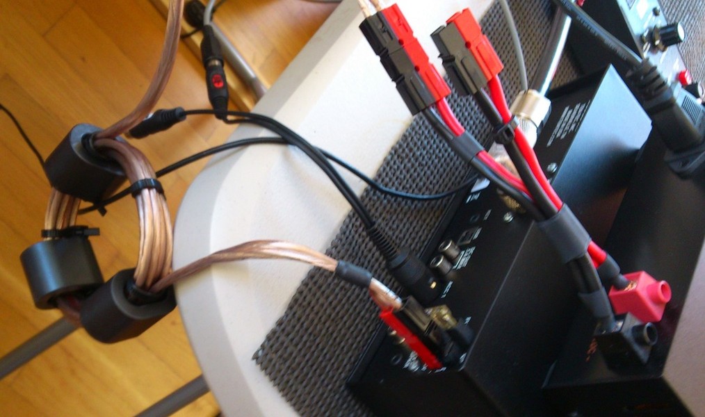
1) Power Supply Choke
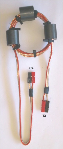
The D.C. choke is pictured on the right.
In a perfect test I would run the transceiver from a floating power source, such as a battery. Since I neither have a battery, or the desire to carry it up the hill to the test site, I wanted to assure the next best thing.
I built a CMC choke for the 13.8 vdc power cord, according to GM3SEK's plan for the Mid-Bands choke. It is pictured on the right.
I replaced my portable power supply (which has the chassis grounded to the Mains earth) with another P.S. which has both D.C. terminals floating.
Finally I will use as short as possible lead to the earth connection at both test points, as well as for the leakage measurements.
The assumption is, any RF current trying to find a path to ground will flow along the ground lead, not back into the power supply.
The connectors are both Anderson Power Poles. The short lead connects to the transceiver, the long lead connects to the Power Supply.
2) GROUND CONNECTIONS

TEST POINT ONE: UNDER THE POLE
At this position I chose to use a ground method which is representative of a real life situation where someone is actually sitting and transimitting directly beside the pole.
I chose a simple stake in the ground.
The stake is a single Spiderbeam galvanized steel ground stake, 75cm long.
It is connected to the transceiver via a 75cm long, 6 sq. mm wire.

TEST POINT TWO: AT THE SUMMER HOUSE
In order to facillitage a better earth connection, I have changed the summer house test location from upstairs to the ground floor. This position is set up just outside of the front door. I am unable to drive a ground stake through the cobblestone floor at this position.
The ground connection is a 1.5m long, 6 sq. mm wire running to the cold water pipe in the bathroom, which is located just inside the front door.
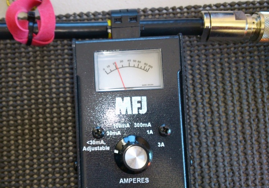
3) RF AMMETER LINEARITY CHECK
(as suggested by Ian, GM3SEK)
Ian suggested that I check the linearity of my RF Ammeter before conducting the tests.
In order to do that, I measured the output of my transmitter at various power levels, using 3 methods:
- Watt Meter
- The transceiver's own digital menu to set the level
- The RF-Ammeter (then calculated the power)
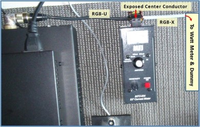
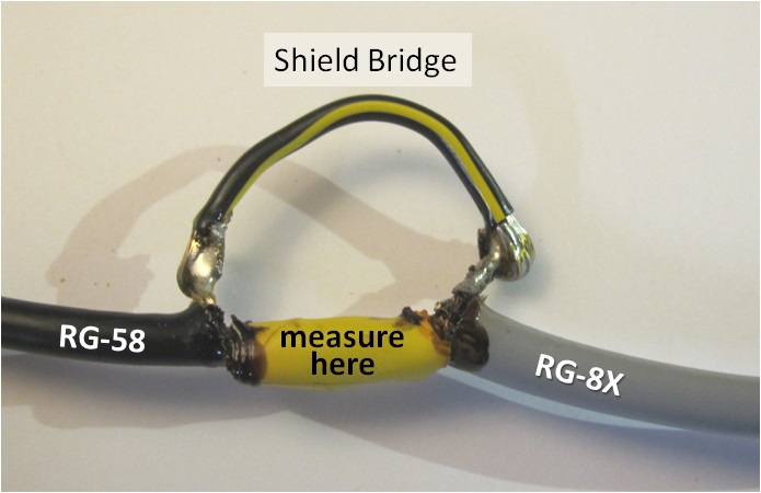
To test the linearity of the RF Ammeter, I first created a special cable for measuring RF current into the watt meter and dummy load. I soldered the center connectors of a short stub of RG8-U and RG8-X together, and insulated the connection with electrical tape. See picture below.
The meter's pickup coil was applied at this point, by simply clamping it over the inner conductors.
I bridged the shield of each stub together with an external copper wire.
The picture below shows the special prepaired coax for measuring:
Before connecting the RF Ammeter, I measured the quality of this funny looking coax by connecting it to a dummy load and scanning it with my RigExpert AA-54 analyzer, from 1 to 31 MHz. I compared the results with a similar scan of a known good piece of RG-213 coax. The results are pictured below.
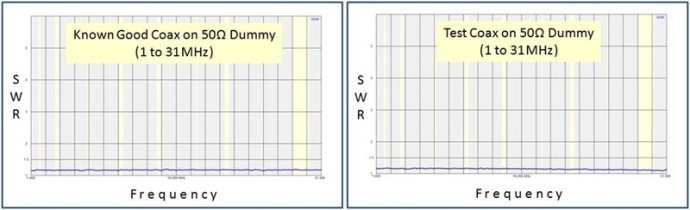
As you can see above, there was no apparent different between my hybird coax and a normal coax at these frequencies.
THE TEST:
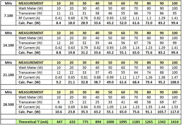
I tested all 4 bands independently of each other in steps of 10w, from 10 to 100w and recorded the following information:
- Power Level shown on Watt Meter
- Power Level shown on Transceiver's Digital Readout
- RF Current as measured with the MFJ-854 RF Ammeter
- Calculated Power Level based on Current squared times 50 Ohms
Each measurement was repeated a second time, making sure that the results of both measurements were the same.
This was a very tedious piece of work, to say the least!
HERE ARE MY RESULTS:
EVALUATION:
In most cases the results were within 10% of each other, but in a few cases they differed by as much as 15%.
Sources of Error:
Setting the power at low levels between 10 and 30w was easy, using the lower scale of the watt meter. Above that point it was more difficult to "guestimate" some of the settings (i.e., 50, 70, and 90w). There were markings on the meter for 40, 60, 80, and 100w.
The watt meter is rated to be within 10% accuracy.
I'm unsure of the accuracy of my eyeballs.
CONCLUSION:
There is no way of knowing which reading was more accurate (watt meter or Ammeter), without investing in more expensive test equipment. Though not perfectl, l feel the RF Ammeter and the Watt Meter correlated close enough across this range to continue with the test at the antenna site.
4) TRANSCEIVER CMC LEAKAGE CHECK
(as suggested by Ian, GM3SEK)
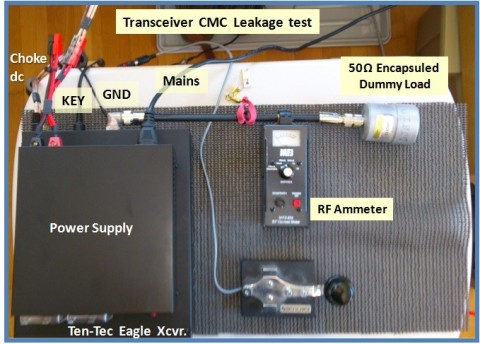
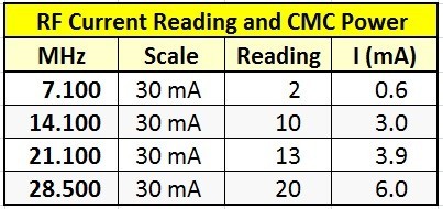
Common Mode Current was measured on each band with 100w into a fully encapsuled dummy load and recorded by band.
Configuration:
- Ten-Tec Eagle Transceiver
- Samlec 1235 P.S. (floating)
- 50 Ohm Dummy Load
- MFJ-854 RF Ammeter
- High Quality RG-213 Coax
- Professional PL Connectors
- CMC Choke on D.C. Leads
- GND: 2.5m wire to cold water pipe
MEASURED RESULTS:
.
NOTES:
GROUND: The ground source is a cold water spicket on the outside wall of the house. The pipe is metal with no PVC between it and the city water supply to the house. The wire between the ground and the transceiver is about 2.5m long.
MEASUREMENTS were taken with the chassis grounded (shown above) but also with the ground removed. Removing the ground resulted in no significant changes to the measurements (less than 10%).
CONCLUSION:
There does not appear to be any common mode current leakage.
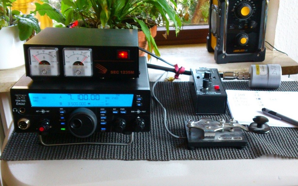
GALLERY:
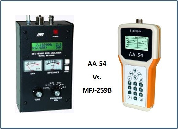
5. ANALYZER SANITY CHECK
Before beginning this long comprehensive test, I wanted to make sure my RigExpert AA-44 analyzer is working correctly.Since I do not have any professional lab-type analyzer to compare it to, I decided to simply compare it to my MFJ-259B.
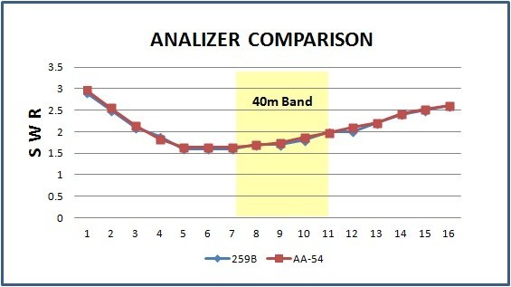
A quick check was made across the 40m band using ANT-B0 to measure and compare.
NO SIGNIFICANT DIFFERENCE WAS FOUND.

N E W

A Short Video by W8JI
N E W
OCFD ANTENNA
PRESENTATION


( Info-Only; NO SALES! )
Spiderbeam on Facebook:


BRAND NEW
from Spiderbeam:

Mini "SOTA" Pole
by Rob Sherwood NC0B

(AUF DEUTSCH)


Spiderbeam FG Pole

Photo: Nischal Nethrananda

A fun film about
Ham Radio Outdoors
(not just in Tenerife)
(English & German)


(nearly) Invisible Pole

An Aerial-51
Sponsored Expedition:
INTRODUCING
Special purpose Aerials:

Ultra-Lightweight antennas for expeditions and stealth applications.
+
(other)
---------------------
UPDATES:
|
|
-----------------
LL-TUNER "S-MATCH"
added to my
symmetrical tuner page.
----------------------
PROGRESSING:
LOTS OF NEW CONTENT IN THE SECTION:


Since JAN-2013
*******************