
CMC TEST - IDEAL TEST ANTENNAS
"Ideal" CMC Test Antennas
.

In an "Ideal" Test:
4 Antennas would be tested:
1) A Common 40m Dipole
2) An Off-Center-Fed Dipole
- Modest Feedpoint Split
3) A Classical Coax-Fed Windom
4) An Off-Center-Fed Dipole
- Radical Feedpoint Split
COLOR COMBINATIONS?
Since it is a Common Mode Current (CMC) test, the antennas are pictured here in colored backgrounds depicting the severity of CMC I expected to find on each antenna's feedline.
ANTENNA REALITIES
UNFORTUNATELY THE REALITY IS SOMEWHAT DIFFERENT!
Due to the size and shape of the space available for testing, as well as the lack of trees on one side, it is only possible to test the antennas in an Inverted-V configuration.
- Care will be taken to keep the feedpoint of all antennas at 10m (33 ft.) height, secured to a fiberglass telescoping pole.
- Where possible, the ends will be kept between 3 to 4 meters high. (10 to 13 ft.). I will add exact heights to the drawings of each antenna after it is in the air and measured.
- Due to the strange configuration of ANT-4 (Radical Split OCFD), it will have very different end heights than the others.
WHY 40 METERS?
- W7EL ran CMC tests on a 10m dipole.
- G3TXQ ran CMC tests on a 20m dipole.
- So why have I chosen to run the tests on a 40m dipole?
This is a fair question and I have chosen it with good reason.
In the past 2 years I have been building and playing with various kinds of antennas, but mostly Off-Center-Fed Dipoles and End-Fed (with coax) antennas. I have encountered some interresting run-ins with CMC on both of these.
One thing I noticed was, with identical end-fed antennas, the 40m version had significantly more trouble with CMC than the 20m version. The only explanation I could think of was, electrically the 40m version was a lot closer to the ground than the 20m version in the configuration I mounted them in (on the 12m fg pole).
The second thing I noticed was that CMC trouble on the OCFD antennas was often severe on the fundamental frequency but significantly less on the harmonic bands. I contribute this to possibly two things:
- Feedpoint electrically closer to the ground on 40m,
- With OCFD, particularly the radical split which had so much CMC problems, the short leg was electrically very short on 40m, but only half as short on 20m.
Since 40m is my favorite band and I typically build antennas on 12m fiberglass poles from Spiderbeam, with an maximum useable height for the feedpoint of 10m, that's what I decided to test.
This way I eliminate the possibility of results run on a 20m antenna not being applicable to 40m.
ACTUAL TEST ANTENNAS
ANTENNA 1
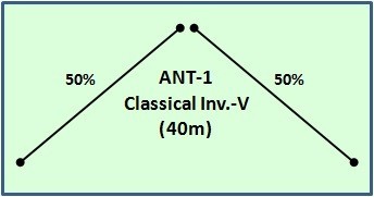
40m DIPOLE
The classical dipole will be tested without a balun, then again with different types of baluns.
One of the tests will intentionally run the coax at a 45 degree angle to the plane of the dipole.
- Leg Lengths: 2x 10.10m
- Weight: 312 gr.
- Weight of 11m RG-174: 195 gr.
- Total Antenna Weight: 507 fr.
ANTENNA 2
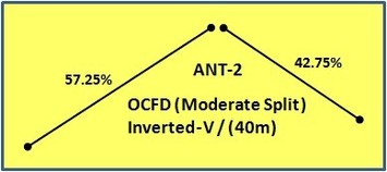
40m OFF-CENTER-FED DIPOLE
This Moderate-Split OCFD is my own design, offering 4-Band Coverage (40/20/15/10m). Its SWR on 40 and 20m is about 2.5:1 and is excellent on 15 and 10m. Length: 20.5m.
ANTENNA 3
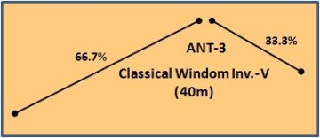
40m OFF-CENTER-FED DIPOLE
Similar to the original "Fritzel FD-3", this is a 40m Windom (or OCFD) with the classical Windom feedpoint split.
ANTENNA 4
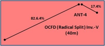
40m OFF-CENTER-FED DIPOLE
This multi band OCFD, originally published by K1POO, had great SWR on 40/20/15/10m but unfortunately suffers from extreme problems with CMC. For that reason it will only be tested with a dual-core 4:1 Guanella Balun. Length: 20.5m.
Variations of the Antennas
The Classical Dipole is the ony antenna that I will test without a balun.
Of course I will also test it with various baluns and chokes.
The Windom/OCFD antennas will each be tested with several types of baluns.
More on this is shown under "The Baluns".
I will also insert a variety of CMC chokes at various points in the feedline and repeat all measurements.
More on this is shown under "The Chokes".
There will be a dozen or more types of tests run on each variation of each antenna.
More on this is shown under "The Tests".

N E W

A Short Video by W8JI
N E W
OCFD ANTENNA
PRESENTATION


( Info-Only; NO SALES! )
Spiderbeam on Facebook:


BRAND NEW
from Spiderbeam:

Mini "SOTA" Pole
by Rob Sherwood NC0B

(AUF DEUTSCH)


Spiderbeam FG Pole

Photo: Nischal Nethrananda

A fun film about
Ham Radio Outdoors
(not just in Tenerife)
(English & German)


(nearly) Invisible Pole

An Aerial-51
Sponsored Expedition:
INTRODUCING
Special purpose Aerials:

Ultra-Lightweight antennas for expeditions and stealth applications.
+
(other)
---------------------
UPDATES:
|
|
-----------------
LL-TUNER "S-MATCH"
added to my
symmetrical tuner page.
----------------------
PROGRESSING:
LOTS OF NEW CONTENT IN THE SECTION:


Since JAN-2013
*******************