
16 SPECIFIC TEST CONFIGURATIONS
BEFORE VIEWING THE TEST RESULTS, it is very important to understand the Road Map through the tests.
It was determined that every test should be run with:
- 4 different lengths of coax:
- Typical Portable Length: 11m for the dipoles; 12m for the OCFD's. This was only slightly longer than the CMC Best Case length, which would be an electrical quarter wavelength using the Velocity Factor for CMC on coax which we estimated to be 0.95).
- Electrical Half Wavelength: The Velocity Factor of the coax (0.66) is used to determine this. (This reproduces the actual characterics of the feedpoint)
- Worst Case Length: Electrical Half Wavelength (Velocity Factor for CMC on coax (0.95) was used)
- Worst Case Length, Skewed: Same as #3, but with the coax pulled away from the feedpoint in the air, running close to one side of the antenna, instead of straight down the pole like with #3.
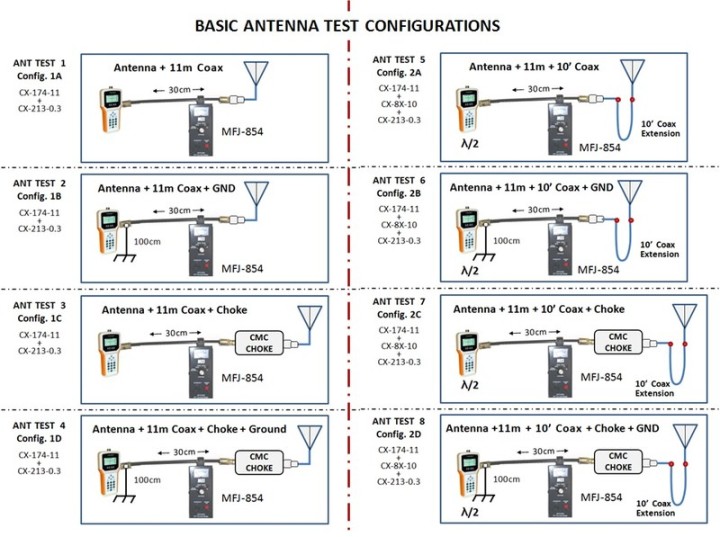
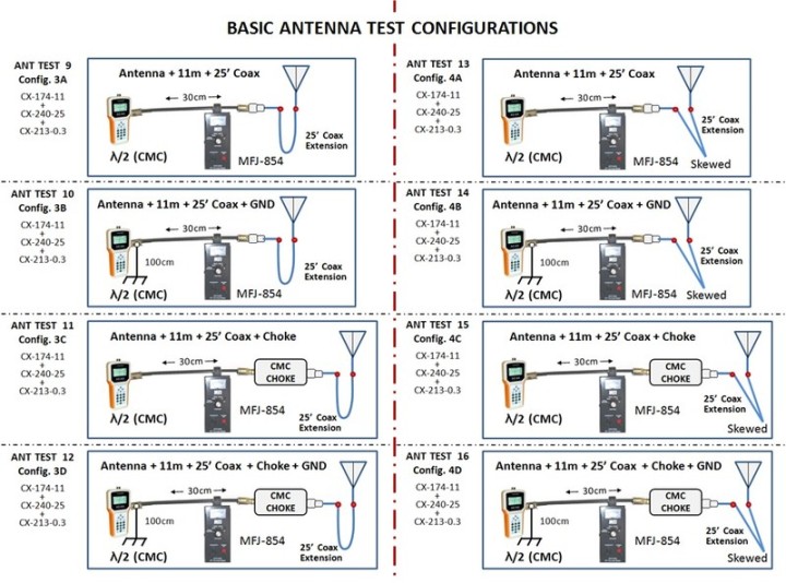
- 4 different configurations:
a) Analyzer or TX: no ground and no choke.
b) Analyzer or TX: coax shield grounded at Analyzer or TX
c) Analyzer or TX: with choke but not grounded
d) Analyzer or TX: with choke and with Analyzer or TX grounded
CONFIGURATION SUMMARY (TOTOAL 16):
Config. 1: Typical Portable length
1a: no ground, no choke
1b: grounded but no choke
1c: with choke but not grounded
1d: with choke and grounded
Config. 2: Electrical Half Wavelength
2a: no ground, no choke
2b: grounded but no choke
2c: with choke but not grounded
2d: with choke and grounded
Config. 3: Worst Case Length
3a: no ground, no choke
3b: grounded but no choke
3c: with choke but not grounded
3d: with choke and grounded
Config. 4: Worst Case Length, Skewed
4a: no ground, no choke
4b: grounded but no choke
4c: with choke but not grounded
4d: with choke and grounded
THIS PATTERN OF 4 SETS OF 4 CONFIGURATIONS
WILL BE FOLLOWED THROUGHOUT THE TEST
FOR ALL ANTENNAS.
TEST CONFIGURATION ROAD MAP:
The configurations above are a bit difficult to read as shown here as a jpeg image.
I have also saved these configurations to a PDF which shows them much clearer.
DOWNLOAD BELOW:
This file shows pictures for the 16 test configurations for testing SWR and other basic antenna characteristics. For measuring CMC, the antenna analyzer was replaced by a transceiver.
BASIC SWR TEST CONFIGURATIONS_small.pdf
PDF-Dokument [747.5 KB]
FINAL NOTE:
- This file and the pictures shown above show the 16 test configurations for measuring SWR and other basic antenna characteristics.
- For measuring CMC, I used the same 16 configurations, EXCEPT the antenna analyzer was replaced with a transceiver.

N E W

A Short Video by W8JI
N E W
OCFD ANTENNA
PRESENTATION


( Info-Only; NO SALES! )
Spiderbeam on Facebook:


BRAND NEW
from Spiderbeam:

Mini "SOTA" Pole
by Rob Sherwood NC0B

(AUF DEUTSCH)


Spiderbeam FG Pole

Photo: Nischal Nethrananda

A fun film about
Ham Radio Outdoors
(not just in Tenerife)
(English & German)


(nearly) Invisible Pole

An Aerial-51
Sponsored Expedition:
INTRODUCING
Special purpose Aerials:

Ultra-Lightweight antennas for expeditions and stealth applications.
+
(other)
---------------------
UPDATES:
|
|
-----------------
LL-TUNER "S-MATCH"
added to my
symmetrical tuner page.
----------------------
PROGRESSING:
LOTS OF NEW CONTENT IN THE SECTION:


Since JAN-2013
*******************