
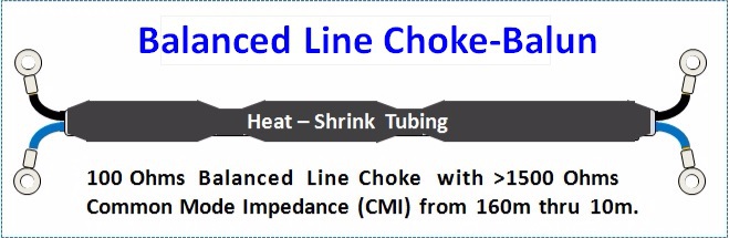
BALANCED LINE CHOKE-BALUN
Very elementary my dear Watson!:
It is "almost" no different than when using coax feedline, especailly if it is for receive-only.
Shown above is a Maxwell Choke for Openwire feedline.
Details of this and a Guanella choke will be added below.
POWER RATING*:
-
SSB: 300 Watts
-
CW: 200 Watts
-
RTTY: 100 Watts
*assumes you use Teflon-insulated wire.
Although it is nearly the same as with chokes for 50 Ohm coax, when we will also be transmitting through the openwire feedline, we must keep in mind that on some bands we may have extremely high voltage present at the end of the feedline. Normal coax or twinlead wire with normal insulation will not work, unless you run only QRP. It will likely have high voltage breakdown.
For this reason it is important to use Teflon insulated wire or Teflon insulated coax for our openwire feedline chokes.
We can use either the Maxwell or Guanella method. Here the same characterics are found as with coax chokes. The Guanella has a higher choking impedance but is frequency limited; the Maxwell has a broader frequency range, but is limited in common mode impedance.
Although the openwire feedline may have 300 to 600 Ohms, using a short unmatched stub creates no problem. After all, we have a matchbox just behind it to compensate for the mismatch.
The Guanella is simple to design and build. Using bifilar windings gives us a 100 Ohm choke (differential current impedance / balanced feedline impedance); using coax, the feedline impedance will depend on the model of coax used (i.e, 50, 75, or 93 Ohms).
The Maxwell presents a slightly bigger challenge:
- RG-142 is a common 50 Ohm Teflon-insulated coax and 5mm (ID) ferrite beads are readilly available for use with it.
- RG-302 is 75 Ohm Teflon-insulated coax and a closer match to the feedline impedance, but its OD is 5.1mm. Common beads will not fit, unless you very carefully drill them out to 5.2mm.
- Here in Germany , DX-Wire offers a very special 75 Ohm Teflon-insulated coax called RG-302 DX-WIRE PTFE Koax.. It has an OD of 4.95mm, and may be used with standard, unmodified 5.1mm beads.
- EVEN BETTER is using twin Teflon-insulated wire (see below).
I can point out sources for building material here in Europe, but I am not that familiar with the sources in the U.S. Someone on that side of the pond can perhaps fill in the gaps.
BEFORE WE BEGIN
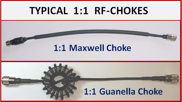
MAXWELL
VS.
GUANELLA
I'm sure by now, most people are familiar with these two names. The picture above should help give clarity about which is which. Although both are shown with PL connectors on both ends, we can replace one with banana jacks and feed with openwire. We can also use parallal wire (bifilar) as described in the balanced Maxwell below. Twisted pair will also work. Just make sure it is Teflon insulated.
Remember:
- The Maxwell is more broad-banded than the Guanella, but has far less Common Mode Impedance.
- The Guanella has far more Common Mode Impedance than the Maxwell, but its effective frequency range is limited.
- Which one is best for the ocasion, depends on the Common Mode Current characteristics of the application.
In applications where the Common Mode Current is not high, the Maxwell will be the balun of choice, provided it is designed with enough CMI for the job. DO NOT ASSUME THAT ANY BALUN WILL WORK. IN GENERAL, ASSUME IT WILL NOT!
A horizontal Openwire Fed Doublet, hanging free and in the clear, usually is fairly well balanced and does not have heavy CMC problems. In these cases, the Maxwell is probably good enough.
However if I turn that same doublet on its side and erect it as an openwire fed vertical doublet, one side is closer to the ground. In this case there will be heavy CMC and the Maxwell will not work, unless you are running very low power. In this case we should use a Guanella.
The problem with a Guanella is, in general they only have high CMI over about 8 to 10 MHz. If we want to cover the entire hf spectrum (160 thru 10m), we should use 3 different baluns.
Most of the time we do not include 160m when building a vertical doublet, so we can get by with two baluns. AND, in many cases we are only building 40 thru 10m so one balun will suffice.
The good news is, we can place the baluns in series, so we do not have to switch back and forth between them.
The bad news is, if our matchbox is marginal and we must enlist the help of a 4:1 balun to help match the antenna on the higher bands, that balun will need to be switched in and out.
Detailed Instructions: Maxwell
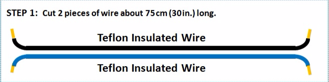
Step 1 the length shown is typical. If you want longer leads on each side, make the wires slightly longer. Although I show the insulation removed here, it is actually easier to insert the wires into the ferrite beads if you do NOT remove the insulation first. So when you build this, CAREFULLY remove the insulation as the last step. TAKE CARE not to cut the strands of wire when removing the insulation.
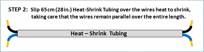
Step 2 doesn't show much detail. It is best to choose a heat-shrink-tubing for this step that has hot melt glue inside. This prevents the tubing from slipping on the slippery surface of the Teflon insulation. I used 6/3 tubing for this. That means the inside diameter before heating was 6mm and after heating it was 3mm.
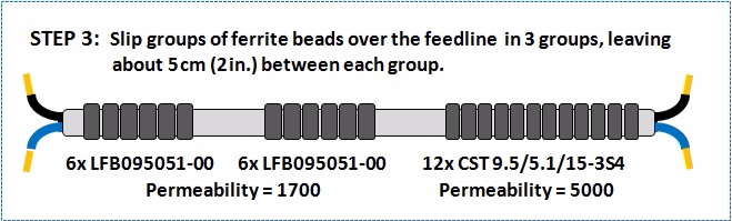
Step 3 shows us the secret to building an effective broadband choke. It is impossible to use just one type of ferrite beads and cover the entire hf spectrum effectively. We have to use two types. Here the CST beads uphold the good CMI on 160 and 80m while the LFB beads uphold it on 10 and 12m. If we just used one or the other, one end would drop off, depending on which one we choose.
The Wireman makes two relatively good chokes (single ended - not balanced) using just one type of bead with a permeability of 2500. His 160m version uses 5 additional beads. Though good, they do not match the performance of the choke shown here. Also, they are not balanced chokes, but you can still use them.
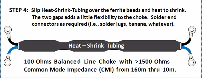
STEP 4 shows the completed choke. Remember, this is a drawing, not a picture. I'm not an artist. In real life the spacing between the 3 sections is a little longer and it looks a bit thinner. This is a long choke, so without dividing it into 3 segments, it would be very stiff and inconvenient to use.
Detailed Instructions: Guanella
IN GENERAL:
- The low bands need toroid cores with higher permeability and higher turn count;
- the higher bands need less permeability and fewer turns.
- 40 thru 10m can be covered with just one balun for barefoot operations but if running a linear amp, you should have two different baluns.
- For working all bands, we will need two, better three baluns.
CORE SELECTION:
- 160 thru 40m #31 Ferrite
- 80 thru 30m #43 Ferrite
- 40 thru 10m #43 Ferrite (will be low CMI on the high bands)
- 40 thru 10m #52 Ferrite (will be low CMI on 40m)
- 20 thru 10m #61 Ferrite
- 80 thru 10m #43 Ferrite (will be low CMI on the high bands)
IMPORTANT: Since no single core covers the entire hf spectrum, if we
must compromise, it is much better to compromise on the high bands,
because Common Mode Current is almost always much worse
on the low bands than on the high bands, due to the antenna
being electrically closer to the ground on the low bands!
CORE SIZE (for SSB & CW):
- For 200w 1x 1.4 in. Core (FT-140-xx)
- For 500w 1x 2.4 in. Core (FT-240-xx)
- For 1000w 2x 2.4 in. Core (FT-240-xx)
- For 1500w 3x 2.4 in. Core (FT-240-xx)
TURNS COUNT:
- For 160m 17 Turns (-31)
- For 80m 15 Turns (-31 or -43)
- For 40m 13 Turns (-43)
- For 40/30/20 13 Turns (-43)
- For 40-10m 9 Turns (-43)
- For 20-10m 13 Turns (-61)
AS YOU SEE, there is no "one size fits all."
Most of the commercial manufacturers will tell you there is, but believe me, they are "Fulla Bulla!"
They are chasing your money, not your best interest.
One very useful tool to help you understand all of this is the lovely colorful chart (or "coulorful" as he calls it) of Steve Hunt, G3TXQ. It is a wonderful graphical view of how these chokes and baluns work: Common-Mode Choke Impedance - G3TXQ
This is what I use for my guideline for building baluns and chokes.
NOT EVERY APPLICATION NEEDS SO MUCH CMI.
If not, then use the Maxwell I described earlier.
But if you have built an antenna with a lot of CMC, then you need a lot of CMI and there is no better way to address it than a good Guanella, designed specifically for the desired frequency range.
Balanced Line Choke/Balun Guidelines:
As stated often above, how much choke or balun you need depends on the application.
The following are general guidelines for typical installations:
- Openwire fed doublet (also called double Zepp): Assuming it is free and in the clear from larger metal objects, it generally is fairly well balanced and will not be too susceptable to additional CMC. In this case a good Maxwell at the antenna tuner, as described above, should suffice.
- Loop Antennas. Here I am referring to full wavelength loops, used on the fundamental and multiple harmonic bands. This is similar to the doublet above and generally the simple Maxwell at the tuner will suffice.
- Off-Center-Fed-Dipole (OCFD), fed with 300 Ohm twinlead or perhaps 400 Ohm Windowline will have a lot of CMC at the feedpoint. Insert the balanced Maxwell at the feedpoint and probably need a Guanella at the antenna tuner. You can try a second Maxwell. It might work, but if not, use the Guanella.
- Vertical Dipole. Similar to the OCFD, and inserting the Maxwell at the feedpoint is a good idea. If you do that, you may be able to get by with a second Maxwell at the antenna tuner. Otherwise use a 1:1 Guanella at the tuner.
to be continued
UNDER CONSTRUCTION

N E W

A Short Video by W8JI
N E W
OCFD ANTENNA
PRESENTATION


( Info-Only; NO SALES! )
Spiderbeam on Facebook:


BRAND NEW
from Spiderbeam:

Mini "SOTA" Pole
by Rob Sherwood NC0B

(AUF DEUTSCH)


Spiderbeam FG Pole

Photo: Nischal Nethrananda

A fun film about
Ham Radio Outdoors
(not just in Tenerife)
(English & German)


(nearly) Invisible Pole

An Aerial-51
Sponsored Expedition:
INTRODUCING
Special purpose Aerials:

Ultra-Lightweight antennas for expeditions and stealth applications.
+
(other)
---------------------
UPDATES:
|
|
-----------------
LL-TUNER "S-MATCH"
added to my
symmetrical tuner page.
----------------------
PROGRESSING:
LOTS OF NEW CONTENT IN THE SECTION:


Since JAN-2013
*******************