
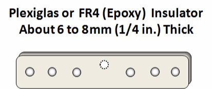
CENTER INSULATOR
( Ultra-Lightweight for $5 )
 Ultra-Lightweight Center Insulator for Openwire-Fed Antennas
Pictured here is a very simple and inexpensive,
ultra lightweight center insulator
for openwire fed dipoles antennas.
It weighs just 1/4 oz. (abt. 7g).
If you were expecting something really elaborate, sorry to disapoint you!
A very important part of building a high-performing antenna is to get it as high into the air as possible. Using high-quality lightweight components, we are able to keep our antennas very light weight, which enables us to raise them high into the air using only a low cost light weight telescoping fiberglass or aluminum push-up pole.
STEP BY STEP INSTRUCTIONS:
Step 1:
BUILD THE BASIC INSULATOR
The insulator is made of plexiglas or Epoxy Board (FR4).
Plexiglass should be about 1/4 inch (6mm) thick.
Epoxy board can be a a little thinner.
Cut the basic insulator: DO NOT DRILL THE HOLES YET.
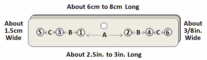
- 2.5 to 3 in. (6 to 8 cm) long
- about 3/8 inches (1.5 cm) wide
Step 2
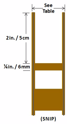
PREPARE THE FEEDLINE
The 6mm high insulation strip will be used for the strain relief. The size is not especially critical but should be kept near this value. This is the piece that fastens to the insulatior with wire-ties.
BE VERY CAREFUL when preparing the two 2 inch wires above the 6mm strip. When trying to trim the insulation from the wires, it is very easy to cut too deeply into the insulation and expose bare wire. This is not too bad but try to avoid that for the bottom 1/2 inch (12mm).
Do not remove the insulation around the wires yet. We will do that later.
TABLE OF DIAMETERS
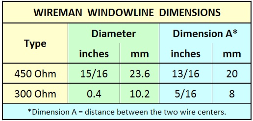
Note: Although there are 4 different sizes of 450 Ohm windowline, they all have the same overall diameter and same distance between the center of the two wires. However the hole size (diameter) will vary, depending on which windowline you use.
With Plexiglas, you should always drill small holes first, then gradually enlarge the size of the hole. If you try to drill larger holes right away, you may crack the Plexiglas.
Step 3
DRILL HOLES
In this step we will drill the holes.
We need 6 holes for the wires and an [optional] 7th hole for attaching a thin rope.
Note, if the dipole is to be used with a fiberglass pole to form a Vertical Dipole, we do not need the 7th hole (center hole).
THIS IS THE ONLY STEP where I cannot specify 100% what you must do,
so please put on your "thinking cap."
There are a few variables here that will determine the hole sizes and the hole spacing.
I can give you guidelines for the spacing when using WIREMAN Ladderline, but the diameter of the holes will depend on the size of wire that you use for the legs, as well as the choice of WIREMAN Ladderline. Wireman Ladderline comes in 5 different sizes.
BEFORE WE CONTINUE, PLEASE STUDY THE PICTURE IN STEP 4, AND THEN RETURN HERE . . .
HOLE SIZE:
You have seen in the picture below how the wires will pass through the holes.
This shows you how to determine how large (diameter) the hole must be.
- Holes 1 and 2 must be large enough for the individual wires of the feedline to pass through, including insulation. Start by drilling very small holes, and then drill the holes slightly larger, then again slightly larger, each time checking to see if the wires pass through. The wire (with insulation) should pass through, yet be a snug fit.
- The antenna wire itself should also be a snug fit. Again begin by drilling a small hole, then enlarge it little by little until the wire is a snug fit.
SPACING DIMENSIONS:
The spacing for the Windowline (Dimension A) is the distance between the centers of the two wires.
You can use the dimension shown in the table above in step 2.
- Mark the middle of the insulator with a permanent ink pin.
- Then drill the two holes each HALF the distance of "dimension A" from the center.
- Try to work as precisely as possible when drilling holes nr. 1 and nr. 2.
DRILL THE HOLES:
- Drill the feedline holes first.
- Then measure the distance from a feedline hole to the outer edge of the insulator.
- Next, drill the outer holes (nr. 5 and nr. 6), positioning them such that they are 1/3 the distance from the feedline hole to the outer edge.
- Finally, drill holes 3 and 4, each centered between their two adjacent holes.
- OPTIONAL: If you will need a 7th hole in the center to attach a thin rope, drill this hole last.
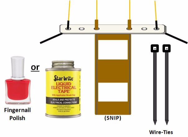
Step 4
INITIAL POSITIONING
This page is just for reference to show you how we begin.
In addition to the two wire-ties, you will need either Fingernail Polish or Liquid Electrical Tape.
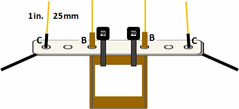
Step 5
Secure Feedline
and
Trim Wire Lengths
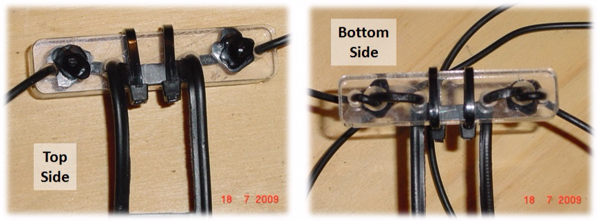
BEFORE YOU BEGIN: look carefully at the real picture at the top of this page (not the drawing on the right). There you see how I positioned the strain-relief strip of insulation.
BEGIN: Fasten the Feedline securely to the center insulation using two (black) UV-resistant wire-ties.
Using dimensions B and C in Step 2 above, cut each wire such that it is of the following length:
- Feedline Stubs: B + 1in. (B + 25mm)
- Wire Stubs: C + 1 in. (C + 25mm)
Next, CAREFULLY REMOVE 1 inch (25mm) of insulation from each wire, and twist the wire strands of each wire tightly together.
Tip: Making sure that the strands of each wire are twisted tight, you may wish to tin only the very tip of each wire with solder. This will keep the strands from coming apart when you push the wires through the holes in the next step.
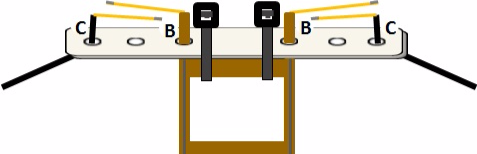
Step 6
BEND WIRES
Bend each wire 90 degrees, flush with the insulation, as shown in the picture.
Step 7
INSERTING THE WIRES
Push the wires on the left through hole nr. 3 and push the wires on the right through hole nr. 4.
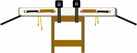
Step 8
SPLICE THE WIRES
One side at a time, push down on the wires from the top, while twisting the wires together from the bottom. Use pliers to assure the wires are twisted firmly together.
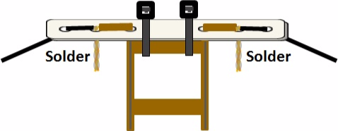
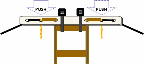
Step 9
SOLDER SPLICES
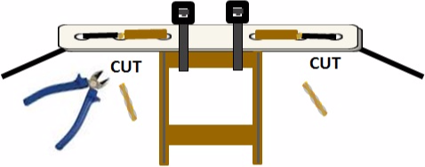
Step 10
TRIM STUBS
Step 11
(final step)
INSULATE CONNECTIONS
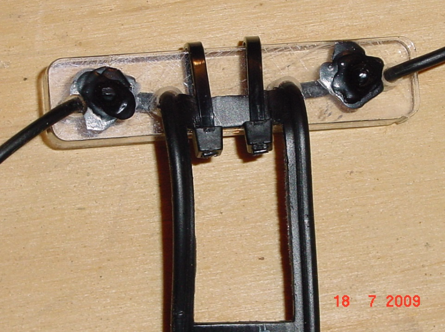
In the example on the right, I used liquid electrical tape to seal and weatherproof the connections.
You may use fingernail polish instead.
DO THIS ON BOTH SIDES.
THIS COMPLETES THE
CONSTRUCTION OF
THE INSULATOR.

N E W

A Short Video by W8JI
N E W
OCFD ANTENNA
PRESENTATION


( Info-Only; NO SALES! )
Spiderbeam on Facebook:


BRAND NEW
from Spiderbeam:

Mini "SOTA" Pole
by Rob Sherwood NC0B

(AUF DEUTSCH)


Spiderbeam FG Pole

Photo: Nischal Nethrananda

A fun film about
Ham Radio Outdoors
(not just in Tenerife)
(English & German)


(nearly) Invisible Pole

An Aerial-51
Sponsored Expedition:
INTRODUCING
Special purpose Aerials:

Ultra-Lightweight antennas for expeditions and stealth applications.
+
(other)
---------------------
UPDATES:
|
|
-----------------
LL-TUNER "S-MATCH"
added to my
symmetrical tuner page.
----------------------
PROGRESSING:
LOTS OF NEW CONTENT IN THE SECTION:


Since JAN-2013
*******************