
Antenna Tuners
Johnson Viking vs. Annecke
THE KING AND HIS CHALLENGER:
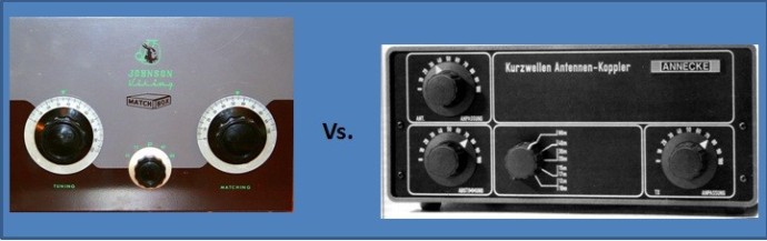 * * * * * * * * * Original * * * * * * * * * * * Vs. * * * * * * * * * * * * * Challenger * * * * * * * * * * *
Many people still believe that the old E.F. Johnson Viking Matchbox is the best matchbox that was ever built; especially when we speak of link-coupled symmetrical tuners.
Although this is definitely wrong, I think it is fair to say that the Viking was the father of the Annecke Symmetrical Coupler.
The Annecke "Symmetrische Koppler" was the logical extension to the Johnson Viking design, but modified to accomodate transistor amplifiers and the WARC bands.
In fact "accomodating the WARC bands" is probably an exageration of the design. At the time Alfred Annecke designed his Symmetrical Coupler, the WARC bands were not on the horizen. It just happens that his design lended itself better to supporting frequencies outside of the original 5 HF ham bands (excluding 160m) than the Viking did.
WHY THE ANNECKE CIRCUIT IS BETTER:
Tube finals encorporated a Pi-Filter in their output that enabled them to compensate for loads which were not exactly 50 Ohms. Matching 3:1 or even 5:1 SWR was no problem for transmitters of the 1960's or earlier.
Transistor finals which came many years later, required a load close to 50 Ohms. The Viking was not always capable of presenting this load to the transmitters.
Realizing this, Alfred Annecke made two fundamental changes to the Viking design which enabled matching a much broader impedance range to 50 Ohms. This was accomplished by adding a 3rd variable capacitor to the design; a 270 pF capacitor in series with the input side of the matchbox, and by adding taps to the input side of the tank circuit.
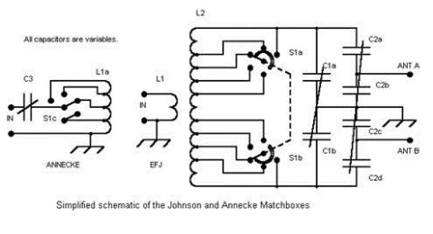
In the following schematic, you can clearly see why the Annecke circuit is superior to the original Johnson circuit:
 Annecke Vs. Johnson Viking
Although the output side (on the right) of both matchboxes is identical, the input side has two subtle differences.
The Annecke circuit is on the far left; the Johnson Viking is in the middle.
Whereas the Johnson input side was simply a link coil, the Annecke had a tapped-coil and a series (variable) capacitor. This enabled the Annecke under certain circumstances to present a much better load to the transmitter than the Viking.
The Annecke is the undisputed winner from a technology standpoint. Both matchboxes had very robust components. Beauty is in the eyes of the beholder, but for me, the Viking was the better looking matchbox.
If you have an old Johnson and feel like I just burst your bubble, don't dispair. It is not difficult to add the Annecke changes to your Viking, and bring it up to the standards of the Annecke. Since the changes were on the low impedance (50 Ohms) side of the link, the components are not subject to high voltage.
A discription of the modification is shown on the next page of my web.
ANNECKE IMPLEMENTATION:
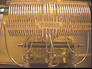
Here you see the two coils of the link-coupling. The larger, thinner coil is on the antenna side of the tank circuit. The smaller, thicker coil is on the transmitter side of the tank circuit.
The longer coil is inserted inside of the thicker coil, with the thicker coil centered in the middle of the longer coil. This is important for maintaining symmetry.
Note that the band switch is physically positioned with its center in the middle of the two coils. It has three wafers. The wafer on the left and on the right switch the antenna coil from both ends simultaneously, keeping it symmetrical. The center wafer (which is the switch that the Johnson Viking Matchbox does NOT have) switches the turns of the coil on the transmitter side of the tank circuit.
The addition of this third switch enables the Annecke to match a much broader impedance range than the Johnson Viking. But the additional switch is only half of the story...
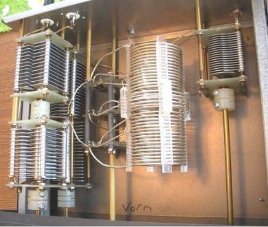
INSIDE VIEW: Annecke Symmetrical Coupler. (200 Watt Version)
Here, you see 3 variable capacitors, 2 on the left (above and below each other) and a smaller one on the right.
The smaller variable capacitor on the right (270 pF, 750v) is the additional 3rd variable capacitor. The Johnson Viking Matchbox does not have this capacitor, but it is very important if you want to optimize the match to a broad range of impedances.
You will need to add this capacitor to the Johnson Viking if you want it to work as well as the Annecke.
Also note that the plate spacing of the capacitor on the right is not as wide as the plate spacing of the two capacitors on the left. That's because the third capacitor (C3) is located on the TX side, where the impedance is generally around 50 Ohms. Voltages are not as high on that side of the tank circuit as they can sometimes be on the antenna side of the tank circuit.
For more info on the mod, see: Johnson Viking Upgrade
SUMMARY AND CONCLUSION:
It is perfectly clear why the Annecke circuitry is superior to that of the old Johnson Viking Matchbox.
This does not make the Johnson Viking a bad Matchbox, but it puts things in their proper perspective.
Henry Fords "Model T" was a classic, but nobody would try to argue that it is a better car than today's Ford Mustang.
If you are into collecting Boat Anchors, you will probably want to leave your Johnson Viking Matchbox "as is". Modifying it would reduce its value to a collector.
However if you are looking to see a significant performance boost with your Johnson Viking Matchbox, you should consider adding the Annecke Mod as described on the next page.


N E W
OCFD ANTENNA
PRESENTATION


( Info-Only; NO SALES! )
Spiderbeam on Facebook:


BRAND NEW
from Spiderbeam:

Mini "SOTA" Pole
by Rob Sherwood NC0B

(AUF DEUTSCH)


Spiderbeam FG Pole

Photo: Nischal Nethrananda

A fun film about
Ham Radio Outdoors
(not just in Tenerife)
(English & German)


(nearly) Invisible Pole

An Aerial-51
Sponsored Expedition:
INTRODUCING
Special purpose Aerials:

Ultra-Lightweight antennas for expeditions and stealth applications.
+
(other)
---------------------
UPDATES:
|
|
-----------------
LL-TUNER "S-MATCH"
added to my
symmetrical tuner page.
----------------------
PROGRESSING:
LOTS OF NEW CONTENT IN THE SECTION:


Since JAN-2013
*******************