
JOHNSON VIKING MATCHBOX UPGRADE (1)
ADDING THE ANNECKE MODS TO THE J.V. MATCHBOX
The Johnson Viking Matchbox is a very good antenna tuner,
but it is NOT the Holy Grail.
Indeed the ANNECKE SYMMETRICAL COUPLER is much closer
to being the Holy Grail than the J.V. Matchbox.
THE PROBLEMS:
The single biggest problem with the Johnson Viking Matchbox is its AGE.
When the J.V. Matchbox was designed:
- We only had 5 hf ham bands: 80, 40, 20, 15 and 10m.
- The WARC bands weren't even in our dreams.
- Transmitters had tubes and could easily match and deliver power efficiently to a 5:1 SWR load.
The world has changed a lot since then:
- We now have 8 hf ham bands.
- Transmitters (transceivers) use transistors in their final amp, and require the SWR to be less than 3:1. In fact many are unhappy with even 2:1 SWR.
- The market's ridiculous strive for smaller rigs and lower cost has resulted in a generation of linear amplifiers which despite using tubes (not transistors), cannot even cope with 3:1 SWR.
- As a result, a matchbox is often required to provide a good enough match on some or all hf bands.
COPING WITH THESE NEW REQUIREMENTS
IS BEYOND THE CAPABILITY OF
THE JOHNSON VIKING MATCHBOX!
THE TWO SPECIFIC PROBLEMS:
- We cannot always match the antenna on all 8 bands
- The match is not always good enough for our transceivers and linear amplifiers
THE SPECIFIC CAUSE OF THE PROBLEMS:
- The small coil on the transmitter side of the link coupled coils has only one setting. It requires more taps and a switch to be able to provide a better match to more bands.
- To improve the match to the transceiver even more, a 3rd variable capacitor must be added in series with the TX input line.
MOD OVERVIEW:
BEFORE ATTEMPTING THIS MOD,
BE SURE YOU READ AND UNDERSTAND
THE INFORMATION PRESENTED ON THE PREVIOUS PAGE:
Overview:
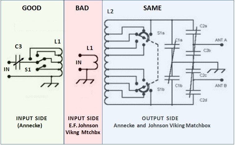
The OUTPUT SIDES of both matchboxes are nearly identical. No changes necessary there.
Changes will be made to the INPUT SIDE (only).
- The pink box above shows the simple "coil-only" input side of the Johnson Viking Matchbox.
- The light green box shows the much more complex input side of the Annecke Symmetgrical coupler.
- The original coil will be maintained.
- We will need to add the additional component of the Annecke to the Johnson Viking Matchbox.
- Since our new Switch "S" will be an additional switch, not synchronized with the original bandswitch, the switching schema will look slightly different.
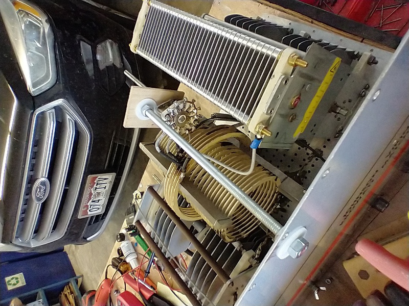
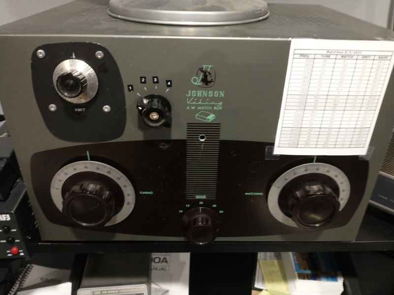
EXAMPLE 275w MATCHBOX:

Here is an inside view of the 275 Watt
Johnson Viking Matchbox.
The Link-Coupling is composed of two coils:
- A long, thinner coil (ANT side)
- A short, thicker coil (TX side)
The longer coil is inserted inside of the shorter coil. The shorter coil is centered on the longer coil.
There are several taps on the longer coil but no taps on the shorter coil.
The first task of the mod is to add a 4 position rotary switch and connect taps to this coil. Electrically, this is a very simple task, but for it to be efficient, the switch should be physically located directly next to the middle of the coil. It will be left up to you to determine how you want to do this.
Where to connect the taps can be seen in the schematic diagram. Beginning at the hot end of the coil, you will want to solder a tap to each turn as you work your way towards the cold end (ground end) of the coil.
SOMETHING TO CONSIDER: The original Annecke has C3 in series with the hot lead running from the hot side of the coil to the center connection of the SO-239 coax input. This requires that both sides of the capacitor are "floating" (i.e., not connected to ground). Most variable capacitors are vorseen to connect one side to ground. By moving C3 from the hot end to the cold end of the coil, you can mount the capacitor with one side grounded to the chassis. See below:

The top circuit on the right shows the TX side (input side) of the Annecke Symmetrical Coupler. It has 3 things that the Johnson Viking Matchbox does not have:
- Taps on the input coil
- A switch to select taps
- An additional variable capacitor
These are the three things that must be added to your Johnson Viking Matchbox if you want to add the Annecke improvements to it.
As mentioned above, the variable capacitor was floating in the original circuit. Theoretically it does not matter which side of the coil you place the capacitor on.
If you place the capacitor on the "cold side" (ground side), AND remove the connection between the coil and ground, you will be able to ground one side of the variable capacitor, as shown in the bottom drawing (Modified for Grounded "C").
Component Considerations:
The procedure for modifying the Johnson Viking Kilowatt Matchbox are exactly the same as those for modifying the 275 Watt version of this matchbox. Of course the KW version requires heftier components.
VARIABLE CAPACITOR:
- 275w Matchbox: 270 pF, 750v
- KW Matchbox: 330 pF, 1.5 kV
SWITCH:
- 3 or 4 Position Rotary Switch*
- 275w Matchbox: 3000v, 15 Amps
- KW Matchbox: Contacts Ratings: 8000v, 25 Amps.
*These are the original Annecke values, which are overkill for the TX (Input) side of the tank circuit. Any decent switch will work for the 275w matchbox, but a very heavy duty switch is required for the Kilowatt Matchbox.
CLICK on the picture below to get an example of the size of components used in the Annecke Kilowatt Matchbox:

USER FEEDBACK:
Hi Rick
There is good news on the EF Johnson KW Box.
I found a ham who did the modification of the KW box to be the holy grail Annecke Koupler. Mainly the input circuit. I attached pictures of how he did it.
The Annecke can match a large range of antenna systems with little sweat.

We'll talk again. Thanks for a nice informative website
.....73.....fred.....KC4MOP
USER FEEDBACK:
Rick,
Its been nearly a year since I asked you about the Annecke mods.
I finally made the changes and really like the improvement.
Once I get it close I can always bring the SWR down even further with the added transmit capacitor. Significantly better than the stock Johnson.
Thanks for posting the info on the mods, the Annecke, and everything.
73,
Bob Mesenbrink
NBØBN


N E W

A Short Video by W8JI
N E W
OCFD ANTENNA
PRESENTATION


( Info-Only; NO SALES! )
Spiderbeam on Facebook:


BRAND NEW
from Spiderbeam:

Mini "SOTA" Pole
by Rob Sherwood NC0B

(AUF DEUTSCH)


Spiderbeam FG Pole

Photo: Nischal Nethrananda

A fun film about
Ham Radio Outdoors
(not just in Tenerife)
(English & German)


(nearly) Invisible Pole

An Aerial-51
Sponsored Expedition:
INTRODUCING
Special purpose Aerials:

Ultra-Lightweight antennas for expeditions and stealth applications.
+
(other)
---------------------
UPDATES:
|
|
-----------------
LL-TUNER "S-MATCH"
added to my
symmetrical tuner page.
----------------------
PROGRESSING:
LOTS OF NEW CONTENT IN THE SECTION:


Since JAN-2013
*******************