
LAB PROOF (2)
By W8JI
Tom Rauch, W8JI, is one of the most renowned antenna authorities of our times. He has an outstanding web site where he shares his knowledge with all of us who are willing to take the time and read it, AND he was the chief architect of the portfolio of Balun products sold by DX-Engineering in the states.
In 2010, Tom conducted a series of lab tests in which he measured the balance obtainable into an openwire feed using various types of baluns. His tests also included testing the original Johnson Viking Matchbox which was a link coupled symmetrical antenna tuner.
I will direct you directly to Tom's web site but there is a lot of information on that one page.
There are two important points that you should read and understand:
- The opening summary of what is important for a balun.
- The chart showing measured results at the very bottom of that page.
Point 1: Tom writes at the top of the page:
Note: Many authoritative articles and technical information sources on balun design ignore voltage, focusing only on current. Focusing only on current is a serious oversight that can result in defective system design.
Equal currents alone do not assure balance, and SWR is not a confirmation of proper system operation.
Consider this:
All systems, both balanced and unbalanced, have exactly equal and opposite currents in each conductor when properly functioning. VOLTAGE is what ultimately determines balanced or unbalanced line or port design.
Point 2: Look for the chart at the bottom of that page:
(it looks like this:)
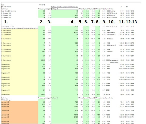
This chart shows 13 collumns:
- Device Tested
- Frequency it was tested at (green background)
- Voltage in Leg A (white background)
- Boltage in Leg B (green background)
- Voltage phase of Leg A (white background)
- Current in Leg A (green background)
- Current in Leg B (white background)
- Voltage phase of leg B
- Unbalance
- Note about the unbalance measurement
- Z1 (Impedance in leg A)
- Z2 (Impedance in Leg B)
- Total Load Impedance
PLEASE FOCUS ON EACH COMPARISON OF 'LEG A' AND 'LEG B'!
Even if you do not understand everything that Tom did, at least you should realize that the values measured in Leg A compared to values in Leg B should be equal or at least close, in order for the balun to function properly.
VERY IMPORTANT:
- "DC unmatched" means "Dual-Core 4:1 Guanella" (Yellow Background)
- "Single core 4:1" is a 4:1 Guanella with both transmisslines wrapped on the same core. (Yellow Background)
Just above the chart, Tom writes the following comment:
Look at how terrible balance is on a single-core 4:1 "current balun" below. A 4:1 single-core "current balun", as presented in "Baluns and Unun's" and used in some commercial designs, forces a system into gross voltage unbalance. It is not a balun. This is what happens when we offer a balun design without understanding or measuring balance.
Comment by Rick, DJ0IP:
THESE ARE MEASURED RESULTS
by one of the industries
most renowned professionals.
HERE IS THE LINK TO TOM'S WEB PAGE SHOWING THIS:

N E W

A Short Video by W8JI
N E W
OCFD ANTENNA
PRESENTATION


( Info-Only; NO SALES! )
Spiderbeam on Facebook:


BRAND NEW
from Spiderbeam:

Mini "SOTA" Pole
by Rob Sherwood NC0B

(AUF DEUTSCH)


Spiderbeam FG Pole

Photo: Nischal Nethrananda

A fun film about
Ham Radio Outdoors
(not just in Tenerife)
(English & German)


(nearly) Invisible Pole

An Aerial-51
Sponsored Expedition:
INTRODUCING
Special purpose Aerials:

Ultra-Lightweight antennas for expeditions and stealth applications.
+
(other)
---------------------
UPDATES:
|
|
-----------------
LL-TUNER "S-MATCH"
added to my
symmetrical tuner page.
----------------------
PROGRESSING:
LOTS OF NEW CONTENT IN THE SECTION:


Since JAN-2013
*******************