
General Configurations for the Tests
Part-1: Basic Characteristics
In Part 1 of the test, we will investigate the basic characteristics of the antenna on the shortest possible coax. This would be typical of a portable operation where the operating position is set up right underneath the pole. It is also very close to being a "best case" configuration for CMC, becasue the coax is only slightly longer than a quarter wavelength on 40m.

TO BE TESTED IN PART-1:
- The Antenna's SWR curves across each of the bands. No ground, just the analyzer.
- The Antenna's SWR curves across each of the bands with the antenna grounded at the analyzer.
- The Antenna's SWR curves across each of the bands with a CMC Choke between the analyzer and the antenna.
- The Antenna's SWR curves across each of the bands with a CMC Choke between the analyzer and the antenna, and with the antenna grounded at the analyzer.
NOTE: The results achieved represent measurements of the antenna
- including any impedance transformation -
that this particular length of coax might cause to the antenna system.
It is NOT the same as measuring directly at the antenna feedpoint.
.
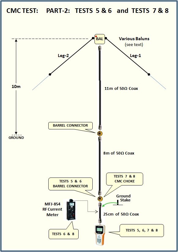
Part-2: Half Wavelength Feedline, &Theoretical Worst Case Characteristics
In the first part of "Part 2" of the tests, we will extend the coax to EXACTLY one half wavelength which repeats the antenna characteristics at the feedpoint (minus the losses in the coax, which are relatively small).
In the second part of "Part 2" of the tests, we will extend the coax further to a length which is an electrical half wavelength as seen by the CMC. This is just slightly shorter than a physical half wavelength.
about an electrical half wavelength, representing the worst case scenerio for CMC. Again we will just be looking at measurements on the analyzer.
SNEAK PREVIEW OF THE RESULTS:
Unfortunately the analyzer was unable to produce enough power to generate enough common-mode-current for me to measure. So much for believing the MFJ advertising!
As a result, parts 1 and 2 will only show the analyzer's measured results in all of these configurations and what effect CMC had on the SWR curves..
Indeed that alone brought some surprises!
.
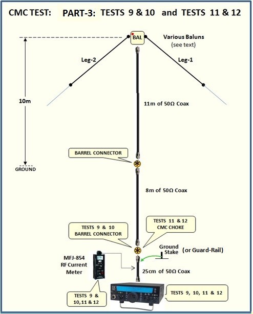
Part-3: On the Air - Absolutely Worst CASE
In Part 3 of the test, we will see what happens when we go On the Air with 100w of power. Analyzers are great tools but will the CMC problem suddenly increase when we apply a little bit of power? How will the various chokes and baluns help us reduce/eliminate the problems?
To make it interesting, we will measure with the coax running perpendicular to the antenna, AND also measure with the coax running away from the antenna at a 45 degree angle, much closer to one side than the other.
Finally, after measuring the CMC in this configuration, we will rotate the antenna 180 degrees and measure again.
Obviously this last test with diagonal coax created a lot of CMC, which gave us a great opportunity to test and compare various RF-Choke technologies.
 The exact length of the coaxial extension will be shown in the results of each test.

N E W

A Short Video by W8JI
N E W
OCFD ANTENNA
PRESENTATION


( Info-Only; NO SALES! )
Spiderbeam on Facebook:


BRAND NEW
from Spiderbeam:

Mini "SOTA" Pole
by Rob Sherwood NC0B

(AUF DEUTSCH)


Spiderbeam FG Pole

Photo: Nischal Nethrananda

A fun film about
Ham Radio Outdoors
(not just in Tenerife)
(English & German)


(nearly) Invisible Pole

An Aerial-51
Sponsored Expedition:
INTRODUCING
Special purpose Aerials:

Ultra-Lightweight antennas for expeditions and stealth applications.
+
(other)
---------------------
UPDATES:
|
|
-----------------
LL-TUNER "S-MATCH"
added to my
symmetrical tuner page.
----------------------
PROGRESSING:
LOTS OF NEW CONTENT IN THE SECTION:


Since JAN-2013
*******************