
Matching OpenWire Fed Antennas
How to best match an openwire fed antenna (e.g., dipole, doublet, double-zepp, loop, etc.) is one of the most disputed topics in ham radio.
THIS PAGE is about two solutions that have worked for me with up to 1kW of power.
I will not go into the details of the numerous other solutions I tried which did not work.
I will show just two methods:
- What I prefer (in theory)
- What I use (in practice)
Explaining how I arrived at this conclusion and especially "why" is way beyond the scope of this web site. Suffice it to say, I honestly have tried every concept on the planet (except one) and have chosen my own favorite method - because it works for me on all bands at all power levels I have run it at, without any problems.
The one method I have not yet tried is the "S-Match", designed by PA0FRI. I have built an S-Match matchbox but haven't found the time to test it and apraise it yet. You can read the basic theory of the S-Match somewhere on this page: Symmetrical Matchboxes
NOW, on to the solutions . . .
VERY IMPORTANT
ALWAYS tune your matchbox with low power (i.e. 10 to 20 watts).
Never tune while running 100w.
Otherwise you have a high risk of blowing the transistors
in your transceiver's final amplifier.
1. My Favorite Symmetrical Matchbox (theoretically*)
As I stated in my introduction to Symmetrical Matchboxes, my favorite matchbox technology for matching symmetrical feedlines is the Link-Coupled Symmetrical Matchbox. Examples of this are Johnson Viking Matchbox and Annecke Symmetrical Coupler. Unfortunately neither of these are manufactured any more, you will probably get hit by lightning before you find one of these on the used market still in good condition. (hi)
The single biggest advantage of these link coupled matchboxes is, the galvanic separation of input and output helps reduce common mode current significantly.
The biggest drawback is the complexity and cost of this type of solution.
The Johnson Viking and Annecke matchboxes are both described on this page:
High Power Symmetrical Matchboxes
And they are compared here:
* It says "(theoretically)" because that is only true as long as the antenna system is relatively well balanced, especially where it attaches to the antenna matchbox. In practice, this is seldom the case. Often, an asymmetrical matchbox with a very good 1:1 Guanella balun between it and the openwire will work better than these link-coupled symmetrical matchboxes.
Rather than worry about finding a Johnson or Annecke, let's focus on what else we can do that will work nearly as good: my "OWF AMS".
The "OpenWire-Fed Aerial Matching System" I propose below has 3 disavantages and 3 advantages compared to the Johnson or Annecke link-coupled matchboxes.
Disadvantages:
- It does not offer the bandpass filter feature of the link coupled tuners.
- It does not inherently impede Common Mode Current (CMC) by design; but we can intorduce additional circuitry to address this effectively.
- It has a tiny bit more loss, but this is really negligable when measuring the signal strength at the other end of the QSO. (Assumes you have tuned the matchbox correctly)
Advantages:
- If the right matchbox is purchased or built, it will have a broader matching range than the Johnson or Annecke.
- Availability; it can still be purchased new today and it is easy to find used matchboxes on the market which may work; albeit with most of these solutions, you will need to use an external balun.
- The cost can be significantly less! (Affordable for most of us.)
2. An OpenWire-Fed Aerial Matching System
(This is the system I have been using for about 15 years now.)
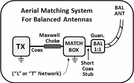
WARNING: Please do not jump to any false conclusions here. Each of the components is special, selected for the specific task. You cannot just substitute any old matchbox or any old balun and expect it to still work properly. Details of each will be given below.
I have always run my openwire feedline all the way into the shack, and then used just a very short piece of coax to connect to the matchbox. This has always worked for me.
Many people I have suggested this solution to have also tried it with 8 to 10 feet of coax, (i.e. the BALUN outside of the house, with a short piece of RG-213 coax running into the shack) and reported good results.
Since I never recommend anything which I have not personally tried, I cannot assure you that this longer coax works, but it sounds like it does. Do your own due diligence.
THE BIGGEST CHALLENGE: IMPEDING THE COMMON MODE CURRENT
I can't stress this point enough. Common Mode Current (CMC) can cause all kinds of havoc in the shack unless it is blocked. Without the help of galvanic separation (link coupling) we must take additional steps to block CMC. The answer sounds easy: Balun. Unfortunately MOST people (most manufacturers of matchboxes as well) choose and use the WRONG balun for this job. More on this topic below.
I will suggest balun and choke solutions that work. Why I have chosen the ones I show is described elsewhere on my web site. There is plenty of material in the sections on Baluns and on CMC.
THE BIGGEST PROBLEM OF ALL: ONE SIZE DOES NOT FIT ALL.
Seems everyone these days wants to have one simple device that can do everything. They expect to buy a single matchbox or balun that will work equally well across the entire HF spectrum, from 160m to 10m. Unfortunately this just does not work very well. Compromises are made and the results are apparent at both ends of the frequency spectrum.
The best solution is to use two different matchboxes and two different baluns. However if we are lucky and choose the right components, we can sometimes get away by using just one of each. It really depends on how much CMC we have on our feedline and this depends on the power level we are running AND the environment around the antenna. It also depends on how we run the feedline. Feedlines should be run perpendicularly away from the antenna - but this is not always possible.
NOW on to the selectionof individual components . . .
The MAIN BALUN:
FIRST AND FOREMOST, THE MAIN JOB OF THE BALUN
IS TO PREVENT COMMON MODE CURRENT
FROM FLOWING ON THE TRANSMISSION LINE.
In this case we are also trying to keep it OUT of the matchbox.
It it not the job of the balun to match the antenna or balance the antenna or anything like that. If you don't understand or agree with that, you are lost here. I suggest you read Roy Lewallen's excellent paper on baluns:
Baluns: What They Do And How They Do It
There are many different types of balun technologies available. Some are better, and some are worse at impeding CMC. The undisputable best in this respect is the 1:1 Guanella balun. Therefore the ONLY balun type we should use for the purpose of keeping CMC out of the matchbox is the 1:1 Guanella. Exception: if the CMC is not to strong, a well designed "Ugly Balun" will also work.
DO NOT USE A 4:1 BALUN FOR THIS JOB !!!
Reason: See TUNER BALUNS
If you have selected the right matchbox, it normally should not require help with impedance matching. If your matchbox is incapable of coping with the high impedance of the antenna, then you may add a 4:1 voltage balun between the 1:1 balun and the openwire feedline. The 4:1 balun is used "in addition to", not "instead of" the 1:1 balun.
Now the problem: As stated earlier, it is very difficult to cover ALL bands with just one device. I suggest having two different baluns, a low bands (80-through 30m) and then a high bands (20 thru 10m). The difference is the ferrite mix of the toroid(s) and the number of turns of wire or coax on it.
If you are determined to use just one balun, then use the Low Bands version.
The 1:1 Guanella balun should be built in the W1JR (Reisert) form. It may be wound with bifilar Teflon-insulated wire, or with coax (RG-58 for 200w, Teflon-insulated coax, i.e. RG-142, for more power). We often see baluns using only enamel-insulated wire or sometimes on wire insulated in Teflon, the 2nd wire just enamel-insulated. In my opinion this is asking for trouble. Go that extra mile and use Teflon.
Low Bands:
- 17 turns on a single FT-240-43 for up to 500w SSB/CW.
- Glue 2 cores together and use as one fat core for up to 1000w SSB/CW.
- Glue 3 cores together and use as one fat core for up to 1500w SSB/CW.
- For RTTY, full power, glue 5 cores together!
High Bands:
- 13 turns on a single FT-240-61 for up to 1000w SSB/CW.
- Glue 2 cores together for up to 1500w SSB/CW.
- Glue 3 cores together for RTTY full power.
NOTE: The reason you need fewer cores for the high bands is because the Curie point of #61 ferrite is twice as high as that of #43.
ALTERNATIVE:
MAXWELL BALUN
The Maxwell balun pictured here is a simple, home-brew balun (or choke). Detailed instructions for building it yourself are found HERE.

ALTERNATIVE
THE UGLY BALUN
I have never understood why people call this an ugly balun. I think it's beautiful! It is kinda big though, so I call it my MONSTER BALUN.
Shown here is a balun I built for use with openwire feedline in 2007. At the time, I used just 22 ft. of RG-213. If I were to build one again, I would use 25 ft. of coax to give it a little higher Common Mode Impedance (CMI) on 80m.
Once again it is suggested to to use two baluns. If only one is used, use the low band version unless you don't work the low bands.
Low Bands:
- Use RG-58 for up to 500w or RG-213 for up to 1500w.
- For 80 thru 30m, use about 25 ft. (8m) of coax on a 4 in. (10cm) diameter PVC pipe.
- If 160m is also required, use 30 ft. of coax (9m).
- Leave a short, 6 to 12 in. (15 to 30cm) stub on the matchbox end and solder a PL-259 connector to it. This connects directly to the matchbox.
- Solder banana jacks to the ANT side of the coax. This is where the OpenWire feedline connects.
High Bands:
- Like above but just 15 ft. of coax.
Note: It is best to separate the turns using nylon rope as shown in the picture. This reduces the mutual coupling between turns, yet maintains the symmetry. Use 1/4 in. (6mm) when working with RG-213 or 1/8 in. (3mm) when working with RG-58. It's not the end of the world if you don't do that; it just works better.
The MATCHBOX:
The biggest mistake people make is thinking “any matchbox should work.”
Whether or not it will, depends on the matching range of the matchbox, AND the ability of the balun to keep CMC out of the matchbox, ESPECIALLY if it is an auto tuner.
My favorite solution is the L-Network with the variable coil in series with the antenna and the capacitor shunted to ground. The variable capacitor should have about 500 pF of capacitance, with switchable additional paralleled capacitance. The Capacitor (bank) must also be switchable between the input and output side of the coil. Since we don’t know the impedance to be matched, having a system that enables us to increase the matching range by adding capacitance is a big advantage.
Purests tell us we should only use a fully symmetrical matchbox. They usually suggest the "Symmetrical L-Network", such as the Palstar BT-1500, or the "Symmetrical Pi-Network" such as the MFJ-976. Then they place the balun on the TX side of the matchbox. All of this is floating (hopfully) with no connection to ground.
Although this is balanced and does work, it requires double as many components, costs nearly twice as much, and has one major disadvantage. As I stated above, due to the sometimes very high or sometimes very low impedances to be matched, often 500 pF of capacitance is not enough for the job. We need to switch in additional capacitance as described above. With the symmetrical "T", we would have to switch in equal values of capacitance on both sides, again doubling the number of components and increasing the complexity. With the symmetrical "L", we must keep two roller inductors syncronized.
I BELIVE IN "KISS". Keep it as SIMPLE as possible.
If we can impede all of the Common Mode Current before it enters the matchbox, then the asymmetrical matchbox will work just fine, has far less complexity and costs a lot less. It also makes it easy to add a single capacitor in tough matching situations.
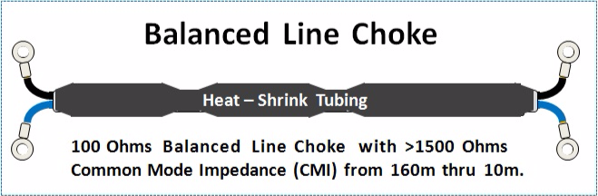
THE CHOKE:
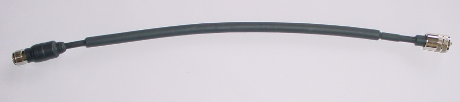
The Maxwell choke pictured here is a simple, home-brew choke using ferrite beads over coax, then covered with heat-shrink tubing.
I usually build my own but sometimes when in a hurry, I just buy one ready-built from DX-Wire. In the states, the Wireman makes a good coax choke similar this. It is their model 8232 which sells for about $30. If you need 160m, then choose the 8233.
SUMMARY:
The concept described above works.
It enables us to match an openwire fed symmetrical antenna with a simple asymmetrical matchbox - simplest case, an L-Network. Unfortunately there are few manufacturers offering an L-Network matchbox. Most offer the "T".
It is impossible for me to predict whether or not "your" matchbox is going to work. You'll just have to try it.
The hardest part for many people to understand is, DO NOT USE A 4:1 BALUN.
Do yourself a favor; don't do it.
If you find your matchbox just doesn't have the matching range needed to match the ultra-high impedances, then when necessary insert an additional 4:1 voltage balun between your 1:1 balun and the feedline, like this:
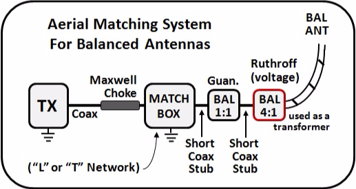
The 4:1 Ruthroff (voltage) balun used on the antenna side of the OWL-AMS is only used as a transformer here, not as a balun. Use #61 ferrite for its core.
REMEMBER:
It is NOT to be left inline all the time.
Only use when necessary.

N E W

A Short Video by W8JI
N E W
OCFD ANTENNA
PRESENTATION


( Info-Only; NO SALES! )
Spiderbeam on Facebook:


BRAND NEW
from Spiderbeam:

Mini "SOTA" Pole
by Rob Sherwood NC0B

(AUF DEUTSCH)


Spiderbeam FG Pole

Photo: Nischal Nethrananda

A fun film about
Ham Radio Outdoors
(not just in Tenerife)
(English & German)


(nearly) Invisible Pole

An Aerial-51
Sponsored Expedition:
INTRODUCING
Special purpose Aerials:

Ultra-Lightweight antennas for expeditions and stealth applications.
+
(other)
---------------------
UPDATES:
|
|
-----------------
LL-TUNER "S-MATCH"
added to my
symmetrical tuner page.
----------------------
PROGRESSING:
LOTS OF NEW CONTENT IN THE SECTION:


Since JAN-2013
*******************