
Antenna Tuners
Symmetrical Matchboxes
Interest in Openwire-Fed-Antennas is growing in popularity.
The best way to match an openwire fed antenna to your transceiver
*used to be:
a SYMMETRICAL MATCHBOX (also called BALANCED MATCHBOX).
Unfortunately there is a lot of confusion around the term
"Symmetrical Matchbox".
In this section I will explain the different symmetrical matchbox technologies in simple terms and share with you my experience, and misfortunes in working with different solutions to this problem.
On the following pages I will show you some of the matchbox products available on the world market.
IMPORTANT: Since creating this page many year ago, I have found an alternative way that fundamentally works just as good. Read Below*
* A good, lower cost alternative exists that will work just as well.
See: Matching Openwire-Fed Antennas
WHY USE SYMMETRICAL MATCHBOXES ?
Symmetrical matchboxes offer the optimum means of matching a symmetrical antenna when fed with openwire feedline. These matchboxes are built symmetrically throughout the antenna side of the matching circuitry.
Once the impedance has been matched symmetrically to 50 Ohms, it can easily be converted to unbalanced using a simple 1:1 balun.
Originally, most symmetrical matchboxes were built using LINK COUPLING. There are additional advantages to this type of circuit. Besides effeciently matching a broad range of impedances, it also adds a significant amount of bandpass selection on transmit as well as on receive. This adds harmonic surpression on transmit and rejects out of band signals on receive, helping to prevent receiver overload. For this reason they are sometimes referred to as "FILTER TUNERS".
Unfortunately Link Coupled antenna matchboxes are complex and expensive to build. There are currently no commercial companies selling this type of matchbox. In fact there are not many commercial symmetrical matchboxes on the market at all, of any type.
SYMMETRICAL MATCHBOX TECHNOLOGIES
- BALANCED L-NETWORK
- BALANCED T-NETWORK
- BALANCED Pi-NETWORK
- LINK-COUPLING
- Z-MATCH
- S-MATCH
1. BALANCED L- NETWORK
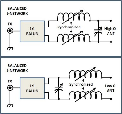
The Balanced L-Network is the simplest traditional way to build a truly balanced matchbox.
It has very good efficiency (very low loss) but it is a bit tricky to implement - both mechanically and electrically. The two roller inductors must be tuned simultaneously, and a means must be found to switch the variable capacitor from the input side to the output side. In addition, in order to match a larger impedance range, additional fixed capacitors must be switched in parallel to the variable capacitor.
A 1:1 Guanella current balun is used on the TX side of the matchbox to convert the 50 Ohms balanced impedance to unbalanced.
BALANCED L-NETWORK ADVANTAGES:
- Low Internal Loss
- Good Efficiency
- Capable of matching a broad impedance range "if" implemented properly.
BALANCED L-NETWORK DISADVANTAGES:
- Requires two [expensive] roller inductors.
- Complex mechanical construction to synchronize the two roller inductors.
- Complex switching is required to switch the variable capacitor from one side of the inductors to the other, and to switch additional capacitors in parallel with the variable capacitor.
- For matching extremely high or extremely low impedances, additional compensating components would be required.
- I am not aware of any Balanced L-Network matchbox that does this - and I only know of one Unbalanced L-Network matchbox that does.
- As a result, performance (efficiency) drops off with very high or very low impedances.
- Usually quite a bit more expensive than Balanced T-Network matchboxes.
COMMENTS:
Using standard components (e.g. 30uH incuctor and 500 pF variable capacitors), the impedance matching range is somewhat limited.
In order to match a broader impedance range, especially on 160m, several additional 500 pF capacitors will have to be switched in parallel with the variable capacitor. In addition, the capacitors much be switchable to both sides of the coil. Although the concept is simple, the implementation is complex.
The switching arrangement must be capable of handling high voltage and high current. This can be done with relays or with a big switch. Either way is expensive. Add to that the cost of two roller incuctors, and you end up with an expensive matchbox.
Although the Balanced L-Network is an efficient matchbox, it may not cover the impedance range you require. Be sure to check this BEFORE you purchast that new matchbox!
Check it out; see: MATCHBOX SHOOT-OUT.
2. BALANCED T- NETWORK
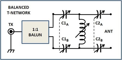
The Balanced T-Network is a relatively simple circuit made up of common components.
Physically, there are only 2capacitors to adjust, plus just one roller inductor (total of 3 adjustments).
Tuning is more difficult than with other circuits which have just 2 components to adjust.
ADVANTAGES OF THE BALANCED T-NETWORK:
- Broad impedance matching range
- Common components
- Only one roller inductor
- No additional switching required
- Lower cost than most other circuits
DISADVANTAGE OF THE BALANCED T-NETWORK:
- Much higher losses than most other circuits
- More difficult to tune than other circuits
- 3 knobs to turn instead of just 2
- Multiple settings can be found which have a good SWR but all of these settings except one result in additional (unnecessary) losses.
-
- Using the wrong settings can result in upt to 50% loss of power or more in the matchbox!
COMMENTS:
The Balanced T-Network matchbox is the cheapest technology for building a fully symmetrical matchbox. It uses only 3 components - one roller inductor and two double-capacitors. There is no additional complex switching necessary.
Unfortunately it is also the technology which has the greatest internal power loss. In addition, tuning this type of matchbox is not always easy, and often the user tunes it wrong, resulting in additional losses.
Despite all of that, I actually own and use one of these! ("Who's perfect?")
I have an MFJ-974B. I use it often for portable events such as Field Day.
Why? Because it is cheap and will match just about anything you throw at it.
AND also because there is currently nothing else available on the market in the 100w class except the ridiculously expensive remote tuner from HamWare!
3. BALANCED Pi- NETWORK
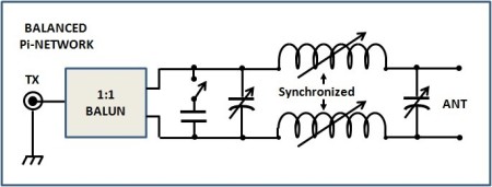
The Balanced Pi-Network is a symmetrical version of the traditional Pi-Network, which was also known as the Collins Filter.
By switching additional parallel capacitors on the TX side, it is able to match a broad impedance range.
The Balanced Pi-Network's efficiency is similar to that of the Balanced L-Network and much better than that of the Balanced T-Network. Its switching requirements are much simpler than that of the Balanced L-Network.
ADVANTAGES OF THE BALANCED Pi-NETWORK:
- Broad impedance matching range.
- Much simpler switching configuration than the Balanced L-Network
- Low loss, high efficiency. (MUCH lower loss than the Balanced T-Network)
DISADVANTAGES OF THE BALANCED Pi-NETWORK:
- Requires two roller inductors (price).
- Higher mechanical requirements. (Requires synchronizing the roller inductors).
- Available only in Europe. (No known manufacturers in the USA).
- PRICE! (VERY EXPENSIVE)
COMMENTS:
Since there are no commercially available Link-Coupled matchboxes on the market anymore, this is clearly the way to go, "if you can afford it." Unfortunately most of us can't afford, or don't want to afford spending that much money on a matchbox. If you happen to be one of the few who doesn't mind spending that much, then take a look at the HamWare AT-615A.
4. LINK COUPLING
NOTE: This is no longer state-of-the-art. There are better/simpler/cheaper circuits for matching balanced feedline-fed antennas now.
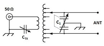
This is a simple link coupling circuit. The antenna side of the tank circuit is fully symmetrical.
Each half of C1 is identical and tuned symultaneously. It must be able to withstand high voltage (3000 volts), even for just 100w operations.
The variable capacitor on the left helps match the circuit to 50 Ohms. This is a luxury. Older link-coupled matchboxes (i.e. Johnson Viking Matchbox) don't have this capacitor and suffer because of it. If you value performance more than looks, it is easy to add this capacitor to any Johnson Viking Matchbox.
 Photo: DJ0IP
The picture on the right is of an Annecke Symmetrical Koppler. Look closely at the long coil. You will see there is a second, larger coil over the middle of the longer coil. This is the "Link" to the transmitter.
The antenna side is on the left in this picture. The bandswitch is located between the differential capacitor and the two coils. The Annecke circuit also has taps on the TX side of the tank circuit (the smaller Link coil); the Johnson Viking Matchbox does not, nor does it have the capacitor on the 50 Ohm side of the tank circuit. These two differences make the Annecke circuit superior to the Viking!
The longer coil, which is the antenna side, has taps, equal distance from each end. This maintains symmetry. Simple tuners use alligator clips or bannana plugs for changing bands. A bandswitch is more comfortable but when several bands are required, it becomes very complex and adds significantly to the cost of the matchbox.
This is a simplified circuit. In reality the Annecke and the Johnson Viking are more complex. They use a double-differential capacitor (4 variable capacitors on one shaft) on the antenna side, in addition to C1 shown in the circuit above. The Annecke also has a tapped/switch coil on the TX side and the 3rd variable capacitor. For more on this, see the page Viking vs. ANNECKE.
THE IMPORTANT THING TO NOTE HERE:
EVERYTHING ON THE ANTENNA SIDE IS COMPLETELY SYMMETRICAL.
This requires more hardware (more cost) than an assymetrical matchbox
or even the other symmetrical matchboxes.
ADVANTGAGES OF LINK-COUPLED MATCHBOXES:
- Excellent symmetry
- Low loss, high effeciency
- The Annecke has a very broad matching range
- Also adds bandpass functionality, which helps on RX as well as TX
DISADVANTAGES OF LINK-COUPLED MATCHBOXES:
- Very high level of complexity
- Limited impedance matching range without the use of complex switching.
- Even if we could find someone to built them, they would be very expensive.
- Johnson Viking Matchbox has a limited impedance matching range
- Its matching range can be significantly improved with a simple modification
COMMENTS:
Unfortunately nobody is willing to build this type of matchbox commercially. The cost of components is just too much. As a result, the only way to get one is either find an old Johnson Viking or an Annecke on the used market, or home-brew one yourself. Most home brew link-coupled projects are for the Z-Match (see below).
Trying to home-brew a general purpose all band link-coupled matchbox is a monumental task, but if you only need one or two bands, it's actually quite simple. I built one for 80 & 40m in a single evening, and it worked great!
5. Z-MATCH
The Z-Match is an interesting matchbox. Like anything else, it has its advantages and disadvantages. Understanding its strengths and weaknesses is key to obtaining satisfactory performance with this circuitry.

The ORIGINAL Z-Match is shown on the right. It is characterized by two link coupled tank circits and two sets of symmetrical antenna connections, one for 3.5 to 10 MHz, and one for 14 MHz to 30 MHz.
It covers all ham bands from 3.5 to 30 MHz, including the WARC bands WITHOUT THE NEED OF A BANDSWITCH, which saves on complexity and cost. However you do have to manually move the openwire feedline back and forth when switching from high bands to low bands.
The 30m band is a bit tricky. Depending on the antenna characteristics, sometimes it matches better when connected to the low band terminals, and sometimes it matches better when connected to the high band terminals. There is a simple rule of thumb: "Try them both and use the one which works best."
No bandswitch means less complexity, a smaller form factor, and it is easier to maintain symmetry throughout the matchbox. It helps keep the cost low. In fact the bandswitch is usually a major cost factor in any matchbox.
Unfortunately, nobody is building these commercially anymore. "Linear Amp UK" was the last company still building these, but they stopped several years ago. In the meantime that company has been sold and I am not sure if the new owners will continue to build any matchboxes or not.
There are plenty of suggestions for building your own Z-Match on the Internet, some with two tank circuits, some with just one. Lots of people have successfully built both types.
ADVANTAGES OF THE Z-MATCH:
- Relatively simple circuit.
- Common, low cost components.
- Very easy to tune.
DISADVANTAGES OF THE Z-MATCH
- You must manually move the feedline when switching from high to low bands or visa verca.
- Although efficiency is fairly good for mid-range impedances, it is much poorer for impedance extremes.
- Very high voltage can develop across the variable capacitors, even at 100w, often resulting in arcing. As a result you are forced to either reduce power of play with feedline lengths.
- No commercial source for these matchboxes.
COMMENTS:
When you read the disadvantages vs. the advantages, you might wonder why anyone would choose this technology. However many people do. The reason is, it is very simple to build one of these, using low cost components. You don't need an expensive bandswitch. In practice, if you put just a little bit of thought into the lengths of the antenna legs and feedlines you use with this matchbox, it is very easy to keep the impedances well within the sweet-spot of the matchbox, where losses are very low.
In Europe you often find used DECCA KW "E-ZEE Match" Z-Match tuners at fleah markets for under $100. It is a great way to get a good symmetrical matchbox at a low cost.
See: LOW POWER ATU's for more on this matchbox.
5a. SINGLE COIL Z-MATCH
"No bandswitch" was a great idea. Swapping antenna terminals when changing bands is not a popular procedure. There had to be a better way. The "Single Coil Z-Match" was devised to enable using just one set of connectors for the feedline. I'm not sure who originally developed this idea, but it was best popularized by Lloyd Buttler, VK5BR.

The picture on the right shows the circuitry of the "Single Coil" Z-match. This is perhaps a misnomer, as all Z-matches use Link Coupling (automatically 2 coils) and indeed, this one added a 3rd coil. But at least it did not have two seprated Link Tank Circuits with separate antenna connections connectors. The biggest advanttage here is, it still required no band witch as such, but it enabled having just one single pair of terminals for connecting the openwire feedline.
Perhaps a better name would be the "Single Tank Circuit Z-Match", not the single coil. As you see, it actually has 3 coils, 2 in the Link plus L3.
Could this be the NON PLUS ULTRA SYMMETRICAL MATCHBOX ?
Unfortunately not. Although it functions as well as the classical 2 tank circuit design, it also suffers from the same drawbacks as the classical Z-Match.
ADVANTAGES: See 5. Z-MATCH (above)
DISADVANTAGES: See 5. Z-MATCH (above)
OK, SO WHAT'S WRONG WITH THE Z-MATCH?
ANSWER: OFTEN, NOTHING. BUT . . . with high impedances or very low impedances, the efficiency of the Z-Match drops off rapidly. In these cases you would be much better off with an Annecke Symmetrical Koppler. Of course the real solution is simply, "fix the antenna."
For a detailed description on this, see: The Effeciency of the Z-Match by Lloyd Buttler, VK5BR.
To "Z" or "Not to Z" ? . . . that is the Question.
There is no clear answer. It is up to the user. The bottom line is, if your impedances are above a few hundred Ohms, you will probably have up to 2 dB of loss. On the other hand, this simple, low cost symmetrical matchbox enables you to work up to 8 bands with just one wire dipole, and it offers good preselection for the receiver.
My Personal Opinion: Yes to "Z". (You mileage may vary.)
Especially for portable operations, I find 2dB loss to be a fair trade-off for being able to work so many bands. I still own a DECCA E-ZEE match and take it along often on trips, knowing that it is a quick and easy way to get on multiple bands.
6. S-MATCH©
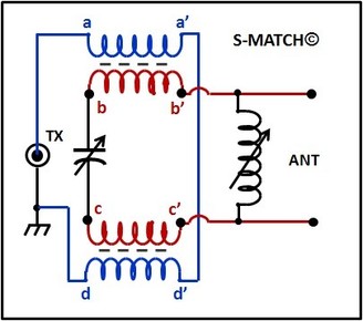
[New Kid on the Block]
The S-Match© is a creation of Fritz, PA0FRI.
The two transformers are wound on a single Toroid. Thus there are only 3 components: Toroid, Roler Inductor, and Variable Capacitor.
I have no personal experience with this circuit and can only repeat what I have read about it on the Internet.
The concept looks very good to me, but:
DO YOUR OWN DUE DILLIGENCE!
ADVANTAGES OF THE S-MATCH©:
- Some users have reported a broad impedance matching range
- Very few components
- Easy to tune
- Low cost
DISADVANTAGES OF THE S-MATCH©:
- Unable to specify the impedance matching range because it will depend on the components one uses when home-brewing an S-Match©.
- Efficiency and loss has not yet been verified by ARRL or other 3rd party.
- Sometimes necessary to move the antenna (by unplugging/plugging) to points b & c (directly across the variable capacitor).
- [To my knowledge] No commercial source.
COMMENTS:
The S-MATCH© looks very promising. It certainly is easy enough to build and should be relatively inexpensive. There are plenty of success stories on the Internet, but all of these just speak about the ease of matching the user's own antenna. I have not seen any test results showing measured results or comparisons to other tuners.
I intend to build one of these in the near future and try it. Unfortunately I too can only report on its matching capability. I cannot measure efficiency.
For more information see: http://pa0fri.home.xs4all.nl/ATU/Smatch/smatcheng.htm

.
Meanwhile, back in today's Real World . . .
CHEAP WORK-AROUND SOLUTIONS:
- Nobody is building and selling a Z-Match.
- Nobody is building and selling a Link Coupled Matchbox.
- Nobody is selling an S-Match, but lots of people are building them (Home Brew).
SO WHAT IS THE INDUSTRY TYPICALLY OFFERING ?
- Christian, DL3LAC is offering a "Balanced-L Matchbox" $$
- Palstar is offering a "Balanced-L Matchbox" $$$
- MFJ is offering a "Balanced-T Matchbox" $$
- HamWare is offering a "Balanced-Pi Matchbox" $$$$$$$
- Kees, PA0LL is offering a "Balanced-Pi Matchbox" $$$$$
The choice is basically between Balanced-L or Balanced-T, unless you want to spend about $1500 to $2000 on a Balanced-Pi Matchbox. (ALL OF THESE ARE EXPENSIVE!)
AND UNFORTUNATELY:
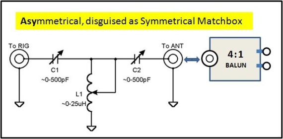
Everyone is trying to sell their cheap work-around solutions to Joe Ham, telling him that an asymmetrical T-Network with a balun is now a symmetrical matchbox. [NOT!]
(See below)
THE PAPER TIGER:
You can fool all the people, some of the time,
You can fool some of the people all the time,
But you can't fool all the people all the time.
THIS IS NOT A SYMMETRICAL MATCHBOX.
And when running high power you will probably have problems with RF in the shack, especially if the matchbox has a 4:1 balun on the antenna side. The balun does not properly function as a balun when the SWR is too high. As a result you will have common mode current in the matchbox and in the shack.
You may notice this by:
- Equipment going into "fault"
- Hot mic or hot key, causing RF burns
- TVI, BCI, etc.
So the next "GURU" said "Do it this way:"
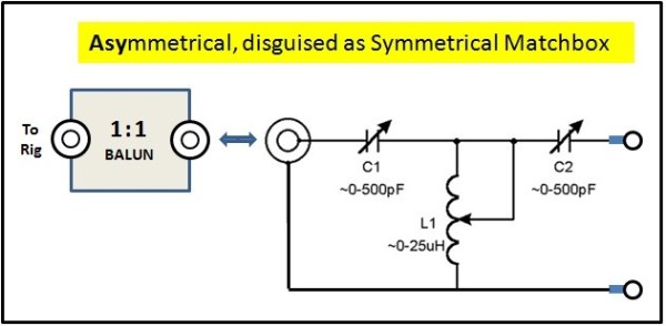
OK, this "looks" better:
- The enclosure of the Matchbox is now floating above ground; nothing is grounded inside the matchbox.
- The Balun is seeing its design impedance.
- Problem is, in practice it only works just a little bit better than the circuit above.
- In many attempts to perfect this, including trying several different types of baluns, I continued to have problems with RF in the shack when running high power.
- Yet when I replaced this with two different high power [true] symmetrical matchboxes, there were no more problems at all !
Bottom Line, this is better than the circuit above, but still just a work-around with hitches. If this is the best you can do, go ahead. But there are much better solutions.
MORE TECHNICAL DETAIL ON THIS TOPIC, BY W7EL, IS AVAILABLE ON THE FOLLOWING LINKS:
AND A GRAPHICAL DIPICTION OF THIS SOLUTION IS AVAILABLE HERE:
THIRD TIME IS THE CHARM: THIS ONE WORKS GOOD:
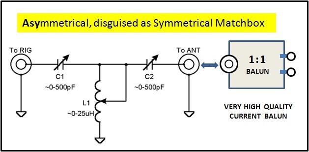
With this circuit I was able to run one kilowatt without burning my fingers on the key, or my lips on the mic. A prerequisite for this is, you have to have a good matchbox which has no problem dealing with the high voltage due to the higher impedance when not using the 4:1 transformation in front of it. The variable capacitors should be rated about 6KV or more.
In my specific case, I used a Ten-Tec Model 238B, which is a very good L-Network.
A good T-Network will also work, if the capacitors are of the values shown here and have wide enough plate spacing.
If it has smaller capacitors (i.e., just 270 pF), it will still work but its impedance matching range will not be as wide as with larger value capacitors.
NOTE: although my Ten-Tec Model 238B has a built-in 4:1 balun, I do not use it for the reasons explained above. Instead I use an external home-brew 1:1 current balun.
I have been using this for the past 20 years.
Recent reports from many others confirm my experience.
For more explanation on why a 1:1 balun is better here than a 4:1 balun, see also:
- "Windom- und Stromsummen-Antennen" by Karl Hille, DL1VU, ISBN 3-910159-14-1, pages 106 and 107.
- Tuner Balun Ratios by Steve Hunt, G3TXQ
- Or this Page: Tuner Baluns

.
NEED YOU WORRY ? . . . and . . . HOW DO YOU KNOW ?
If you are running low power, up to 100w or so,
you can probably use any of these circuits shown on this page
without incurring any problem.
(Even the cheap work-arounds will work.)
If you have a little problem with RF in the shack, simply insert an RF Choke (beads over coax) in the transmission line between the matchbox and transceiver and your will probably be OK.
IF YOU ARE RUNNING HIGH POWER (500+w)
YES, YOU SHOULD BE CONCERNED.
HOW YOU WILL KNOW:
- You may have RF all over the shack.
- Transceivers or Amplifiers may be randomly going to FAULT condition.
- You may have interference with other equipment such as televisions or telephones.
- You will burn your lips on your mic and your fingers on your key.
IN THIS CASE YOU SHOULD FOLLOW THESE PRIORITIES:
- Get yourself a good, high power symmetrical matchbox, like a 1KW Annecke Symmetrical Koppler, Johnson Viking Matchbox, MFJ-976, Palstar BT-1500 or AT-2K-BT (BT=Balanced Tuner. It must be the model with "BT", not the previous model).
- If you only need one or two bands, consider home brewing a symmetrical tuner.
- If a symmetrical tuner is not an option at this time, then use the circuit showing a 1:1 current balun on the antenna side of the matchbox.
- Use either of the other two in a pinch, but don't be surprised if you get some shocking results. In this case it usually helps to insert an RF-Choke (beads over coax) between the matchbox and the amplifier.


N E W
OCFD ANTENNA
PRESENTATION


( Info-Only; NO SALES! )
Spiderbeam on Facebook:


BRAND NEW
from Spiderbeam:

Mini "SOTA" Pole
by Rob Sherwood NC0B

(AUF DEUTSCH)


Spiderbeam FG Pole

Photo: Nischal Nethrananda

A fun film about
Ham Radio Outdoors
(not just in Tenerife)
(English & German)


(nearly) Invisible Pole

An Aerial-51
Sponsored Expedition:
INTRODUCING
Special purpose Aerials:

Ultra-Lightweight antennas for expeditions and stealth applications.
+
(other)
---------------------
UPDATES:
|
|
-----------------
LL-TUNER "S-MATCH"
added to my
symmetrical tuner page.
----------------------
PROGRESSING:
LOTS OF NEW CONTENT IN THE SECTION:


Since JAN-2013
*******************