
EFFECTS OF COMMON MODE CURRENT ON OCFD
PART-1: The Effect of CMC on SWRmin
It was observed that the presence of Common Mode Current on an OCFD antenna caused the frequency of minimum SWR – hereafter referred to as SWRmin – to rise. A test was devised to analyze this closer.
Note: SWRmin ≠ Resonance; it is typically 20 to 30 kHz higher than resonance.
In order to investigat this, I first built a dipole antenna (fig. 1a below) and trimmed it for an SWRmin of 3.450 MHz. The balun (B1) was a 1:1 Guanella balun with 17 turns of coax on an Amidon FT-240-43 Torid. The coax was DX-Wire DXW-142 (similar to RG-142). It is shown on G3TXQ's color charts has having >8k Ohms of Common Mode Impedance (CMI) on 80m.
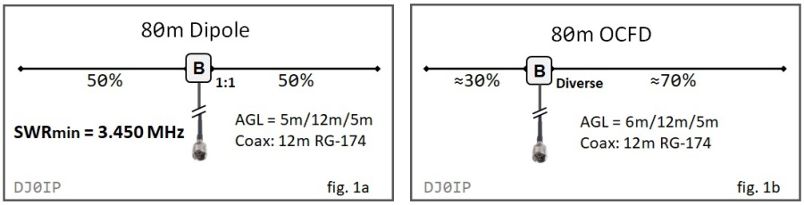
Once the antenna was trimmed for 3.450 MHz, I removed the balun and inserted it about 30% from one end. I soldered the wires together where the balun had been.
I measured SWRmin again: It was basically unchanged, and the SWR was 1.95:1 at 3.450 MHz. This was to be expected, as resonance does not change on a halfwave antenna, simply by moving the feedpoint.
IMPORTANT NOTE: Over the next two years I made and recorded about 500 measurements on the antenna in fig.1b, testing various baluns and balun/choke combinations. Measurements made on the same antenna, but on different days would sometimes show SWRmin ±10 kHz from each other. This was probably due to changes in the weather.
With this "stake in the ground" measurement of SWRmin, we can now investigate several different baluns and balun/choke combinations and observe the effects of CMC on SWRmin.
The second test was made with B2, basically an 1:1 Guanella balun similar to B1, but wound onto an Amidon FT-240-31. According to the color chats of G3TXQ, this should have about the same Common Mode Impedance (CMI) as B1 (>8k Ohms) on 80m, but be mostly resistive, not reactive. SWRmin also 3.450 MHz, with an SWR of 2.1:1.
The next test was using B3, a Balun Designs Model 4115 Dual-Core 4:1 Guanella balun. It has 11 turns of bifilar windings on each FT-240-52 core. According to the G3TXQ color charts, this would be about 1k Ohms (each), but when wired as a 4:1 balun, they are (CMC-wise), effectively wired in parallel. Thus the CMI of B3 is about 500 Ohms on 80m. The SWRmin is at 3.890 MHz (440 kHz higher than it should be); SWR = 1.41:1.
B4 is a "Hybrid Balun", (a.k.a. "Compound Balun"). It has a 4:1 Ruthroff (voltage) balun on the antenna side and a 1:1 Guanella on the TX side. The Guanella is the same choke used in B1. Its CMI is shown as >8k Ohms on G3TXQ's chart, SWRmin is 3.430 MHz, with an SWR of 1.64:1.
B5 is a Dual-Core 4:1 Guanella balun with 12 turns of twisted pair wire wound onto each of the Ferroxcube Toroids (similar to FT-140-43). From the G3TXQ color charts we see that each choke alone has about 2k Ohms of CMI, thus the balun has (CMI wise) about 1k Ohms on 80m. It's SWRmin is 3.530 MHz and its SWR is 1.08:1. This may "look" good, but it's not. Its SWRmin is about 100 kHz too high.
B6 is a Dual-Core 4:1 Guanella balun with 10 turns of twisted pair wire wound onto each of the Ferroxcube Toroids (similar to FT-114-43). G3TXQ did not show any data for these small toroids on his color charts. My guess is that each choke has about 1200 Ohms of CMI, thus the balun has (CMI wise) about 600 Ohms (estimated) on 80m. It's SWRmin is 3.690 MHz and its SWR is 1.59:1. This also "looks" good, but it's not. Its SWRmin is about 150 kHz too high.
B7 is a Dual-Core 4:1 Guanella balun with 17 turns of twisted pair wire wound onto each of its Amidon FT-140-43) cores. From the G3TXQ color charts we see that each choke alone has about 8k Ohms of CMI, thus the balun has (CMI wise) about 4k Ohms on 80m. It's SWRmin is 3.480 MHz and its SWR is 1.41:1. This may "look" good, but it's not. Its SWRmin is about 100 kHz too high.
B10 is an ultra-light version of B4, a Hybrid Balun but using smaller Ferroxcube cores, similar to the FT-114-xx cores. It's 17 turns of thin RG-178 coax is wound on a stacked pair of cores, similar to the FT-114-43, giving it about 6~7k Ohms (estimated) of CMI on 80m. Its SWRmin is 3.430 MHz, and SWR is 1.54:1.
B11 is an light version of B4, a Hybrid Balun but using smaller Ferroxcube cores, similar to the FT-140-xx cores. It's 17 turns of coax on the 1:1 Guanella gives it about 7k Ohms (estimated) of CMI on 80m. Its SWRmin is 3.430 MHz, and SWR is 1.59:1.
Some additional baluns were tested but the results of testing these 9 baluns is sufficient to help us understand the effect of CMC on the antenna. The chart below shows a summary of what was measured above:
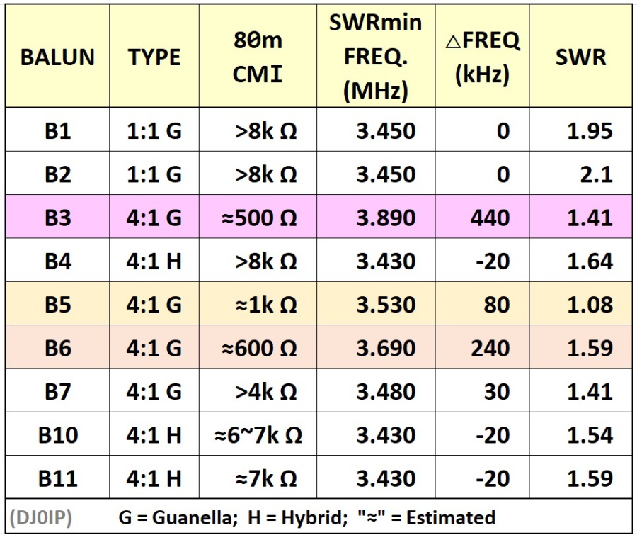
This chart clearly show us what happens to the frequency of minimum SWR (SWRmin) when the balun has insufficient Common Mode Impedance (CMI).
SUMMARY OF WHAT WE SEE IN THE CHART:
We shall ignore the 1:1 baluns because they do not match the impedance.
------------------------------------
THE 4:1 GUANELLA BALUNS:
B3 is miserable. It has the wrong ferrite mix (#52 instead of #43 or #31), and far too few turns of transmission line.
B5 is much better (than B3), even though it is built on much smaller Toroids. It has too few turns of transmission line, causing its CMI to fall short of what is required to drop SWRmin to (or near) 3.450 MHz.
B6 is poor, but it has tiny little Totoids and just 10 turns per core. As stated above, we can only guess at its CMI, as I do not have a dual-port VNA. However, despite these two points, it still performs better than B3, which has two FT-240 cores and about the same number of turns. This is a clear indication that B3 is using the wrong ferrite mix for this application.
B7 is fairly good. It's CMI of about 4k Ohms places SWRmin at 3.480 MHz, which is only about 30 kHz too high.
In summary, it seems an optimum dual-core 4:1 Guanella balun is very close on its own to being good enough. Unfortunately, it also seems that none of the commercial balun OEMs have such a product in their portfolio. Instead, they use Toroids with lower permeability and too few turns of transmission line.
--------------------------------
THE 4:1 HYBRID BALUNS:
At the time I began this field test (March 2015), to my knowledge there were no commercially available hybrid baluns. I learned of the hybrid balun reading Andrew Roos' (ZS1AN) paper in QEX, however it seemed (IMO) to be built backwards.
B4 was my first attempt; my first experience ever with a hybrid balun. Using the G3TXQ color charts, I designed the 1:1 Guanella for 8k Ohms on 80m. I tested the 4:1 Ruthroff (voltage) balun on #61, #52, and #43 toroids and several different turn-counts, observing the SWR curve of each across the HF spectrum. #61 was the clear winner.
To my pleasant surprise, SWRmin using this technology was very close to that of the antenna configured as a center-fed dipole.
B10 was my second hybrid balun. I wanted to see if a very lightweight version would still fend off Common Mode Current. As you see from the chart, it did; at least as far as SWRmin is concerned. Later power tests (into a 200 Ohm 'resistive' dummy load) were satisfactory.
B11 was my third and final hybrid balun. It also had an SWRmin at 3.430 MHz. Later power tests proved it to be ok for 600 watts (intermittantly: string of CW dashes at 5wpm for 10 minutes, with no warming).
In summary, it is clear that CMC causes SWRmin to skew up the band. It also seems to be directly related to lack of CMI in the balun. However, as we shall see in Part-2 below, this is not the only factor affecting SWRmin.
The hybrid balun technology seemed to work quite well with an 80m OCFD antenna. During the summer of 2015, DL5CW used a prototype (with B10), operating OZ/DL5CW, winning 1st Place Overall World-Wide in the IOTA Contest ("Island Expedition Class"-CW).
What more could we want? (!)
---------------------------------
HOW MUCH CMI DO WE REALLY NEED?
According to Tom Rauch (W8JI), there is no single answer to this question. Different circumstances can require different amounts of CMI, sometimes more, sometimes way less.
My next test was to try and ascertain how much CMI is required, at least for "my OCFD" at "my QTH". In order to do this, I repeated the tests above twice, first by adding a 1:1 Maxwell choke directly to each balun; then adding a 1:1 Guanella choke to each balun. Here are the results:
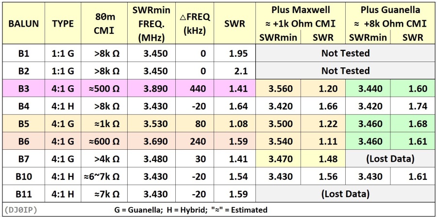
Note: B11 was tested in 2017, 2 years after I began these tests. I cannot find where I stored the data when adding the Maxwell and Guanella Chokes. Also lost some of B7 data.
B3, the commercial dual-core 4:1 balun, looked a lot better after adding the Maxwell Choke. Adding the Guanella choke brought its results in line with the hybrid baluns. Of course, this had basically converted it into a hybrid balun!
B5 was not too bad on its own. The Maxwell choke brought it within 50 kHz of where it shoud be. The Guanella choke brought it in line with the hybrid baluns.
B6 was not very good on its own. The Maxwell choke improved it, but SWRmin was still about 100 kHz too high. The Guanella choke brought it in line with the hybrid baluns.
B7 was almost good enough; the addition of the Maxwell choke brought SWRmin within 20 kHz of where it should be. Unfortunately I could not find the data for where I added the Guanella choke. That test was in 2016 and now, 6 years later, I cannot recall the results.
B4 and B10, did not improve nor change much with the addition of the chokes. This indicates that they were already good enough.
IDENTIFYING TRENDS:
In order to identify trends in all of this, I have rearanged the order of the baluns in the chart, placing like-technologies together. By doing this, we can
better see how different changes affect the Common Mode Current on the feedline.
NOTE: 8 years later I tested the DG0SA Dual-Transmission Line choke in the hybrid balun. Its results have been added to the bottom of this chart.

Note that the dual-core 4:1 Guanella balun (B6) with 10 turns (each core) on FT-114-43's performed better than B3 with 11 turns (each core) on FT-240-52's.
CLEARLY THE HYBRID-BALUN IS SIGNIFICANTLY SUPERIOR TO THE DUAL-CORE 4:1 GUANELLA BALUN.
All three sizes of my Hybrid-Balun performed the same in these tests. Obviously there will be a difference in power handling of different size
Hybrid-Baluns.
In subsequence years, Spiderbeam has built and sold several hundred of these antennas using the mid-size Hybrid-Balun (i.e., 2x FT-140 cores). It is rated at 600 Watts SSB/CW and 200 Watts
digi-modes. Several users report running it at 1kW SSB with no problems.
CONCLUSION OF PART ONE:
From these tests, based on knowing the actual frequency of minimum SWR (SWRmin) of the antenna from testing it as a normal center-fed dipole, it is clear that:
- Common Mode Current causes the feedline to become part of the antenna,
- Thus changing its frequency of minimum SWR. Speciffically, CM current on the feedline causes SWRmin to skew higher in frequency. The higher the magnituce of CM current, the higher up the band it skews.
- The Hybrid Balun, at least at this installation, was certainly the best solution.
- As CMI increases, SWRmin decreases, until it reaches the point where there is [almost] no CM current on feedline.
- Once you have reached the point where SWRmin is approximately the same as with a standard center-fed dipole of this length, adding more CMI does not improve anything.
_______________________________________________________________
PART-2: ANOTHER TEST TO SEE IF CMC IS ON THE FEEDLINE
Whenever the impedance of the transmission line does not equal the feedpoint impedance of the antenna, the transmission line acts like a transformer, transforming the impedance along its length. This is known as Transmission Line Transformation (TLT).
As a result, measuring the SWR at different places along the feedline shows different results, albeit the difference is small whenever the feedline impedance is a close match to the feedpoint impedance (i.e., <2.5:1).
Common Mode Current (CMC) has a much different influence on the antenna. When CMC is present on the feedline, the feedline becomes part of the antenna . . . and radiates. But that's not all! Since the feedline is part of the antenna, it also changes the resonance and frequency of minimum SWR (SWRmin) of the antenna !
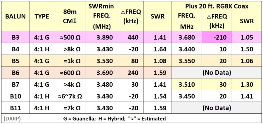
To test this, I began by re-testing each balun with the original length of coax (15 meters - about 59 ft.), and then add a short length of coax to the feedline and tested for SWRmin again. For this test I added 20 ft. of RG8X to the feedline:
Note: these tests were run 5 to 7 years ago. In some cases I cannot find where I saved the data. I am certain I tested this; I just misplaced the results.
B3 was already determined in Part-1 to have CMC issues. Here we see that adding just 20 ft. of coax caused SWRmin to skew 210 kHz downwards.
This is significant! And BAD!
We don't want SWRmin to change every time we connect a different length of coax to the antenna.
The REASON that the frequency of SWRmin change so much when adding just 20 ft. more coax is, the feedline has become part of the antenna because the balun
is doing such a poor job of blocking Common Mode Current. The feedline is radiating.
B5 also skewed slightly, but up the band 20 kHz.
B7, which looked quite good in Part-1, skewed 30 kHz up the band.
B4 and B10 also skewed higher in frequency, but only 20 kHz.
-----------------------
SUMMARY:
Fundamentally there were small changes in SWRmin and level of SWR in all cases but most were quite small. B3, which has by far the lowest CMI, had significant changes.
This would be very bad if the antenna is to be used portable - because the length of the antenna would have to be re-trimmed, each time we change the length of coax.
DISCUSSION:
It has been seen by measurements on real antennas, not modeling, that baluns with low SWR result in significant levels of Common Mode Current.
The belief that only 500 to 1000 Ohms of CMI is all that is required for an OCFD balun could not be substantiated in these tests.
To the contrary; it appears that at least 4k Ohms of CMI is required. Few 4:1 current baluns can achieve this amount.
The antenna was erected pretty much in the clear. In installations with nearby obsticles, even more CMI will be required.
As a result, it is my opinion (and just my opinion) that 6k Ohms of CMI should be the target for our OCFD baluns.
8k Ohms is easily obtainable with a single 1:1 Guanella choke, and 8k Ohms is my recommendation, in order to have additional CMI in reserve in case the installation is not optimum.
I WELCOME ALL OTHER INTERPRETATIONS OF THE ABOVE.
ALL of the measured data is available in individual files that may be viewed in the freeware software "AntScope" from RigExpert.
FINAL NOTE:
ALL CMI values shown in this Field Test were based on G3TXQ's color charts:
http://www.karinya.net/g3txq/chokes/
_______________________________________________________________


N E W

A Short Video by W8JI
N E W
OCFD ANTENNA
PRESENTATION


( Info-Only; NO SALES! )
Spiderbeam on Facebook:


BRAND NEW
from Spiderbeam:

Mini "SOTA" Pole
by Rob Sherwood NC0B

(AUF DEUTSCH)


Spiderbeam FG Pole

Photo: Nischal Nethrananda

A fun film about
Ham Radio Outdoors
(not just in Tenerife)
(English & German)


(nearly) Invisible Pole

An Aerial-51
Sponsored Expedition:
INTRODUCING
Special purpose Aerials:

Ultra-Lightweight antennas for expeditions and stealth applications.
+
(other)
---------------------
UPDATES:
|
|
-----------------
LL-TUNER "S-MATCH"
added to my
symmetrical tuner page.
----------------------
PROGRESSING:
LOTS OF NEW CONTENT IN THE SECTION:


Since JAN-2013
*******************