
The Battle of Baluns Tests
FIELD TESTS
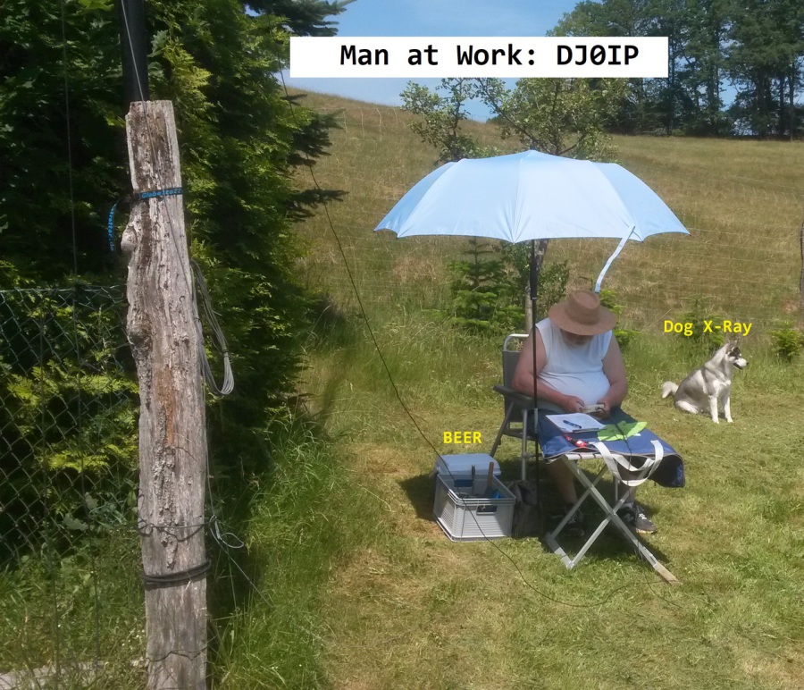
The first thing you need is a field. On hot days you need some beer. And of course you need a watch dog to make sure nobody steels your beer.
A large umbrella is beneficial. It keeps you dry when it rains. When the sun shines, it gives you shade.
When it snows, you need coffee.
And then you need patience;
lots of patience.
The Battle of Baluns is divided into 2 groups of tests:
-
Preliminary Tests
-
Comprehensive Tests
The Preliminary Tests will be conducted with 1/2 wavelength of brand new RG-58 coax that was tested and measured to be exactly 1/2 wl at 3.480 MHz. 3.480 MHz was the targeted resonant frequency of this antenna because that seems to be a sweet spot for 80m OCFD antennas.
The goal of the preliminary test was to determine where the antenna appears to resonate when using just the balun at the feedpoint. Several different baluns were tested. See the Components page to view the specs of the baluns tested. The details and procedures for the preliminary test are described below on this page.
The Comprehensive Tests will add various chokes to the antenna feedpoint, in addition to the balun, and then examine how the choke affects the apparent resonance and SWR of the antenna.
The test is quite complex and explained in detail on the page Comprehensive Analysis.
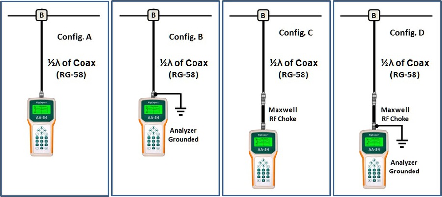
The Preliminary Tests will consist of 4 configurations:
TEST PROCEDURES:
For the initial preliminary tests I am going to focus only on the two lower bands.
For each configuration I will make a suite of 3 measurements:
- Make a 30 MHz scan, centered on 16 MHz. So we will see 1 to 30 MHz.
- Make a 1 MHz scan, centered on 3.700 MHz. So we will see 3.200 to 4.200 MHz
- Make a 1 MHz scan, centered on 7.200 MHz. So we will see 6.700 MHz to 7.700 MHz.
Configurations:
Using ½ wl of coax, cut for 3.500 MHz.
A. Balun (only), coax, then Analyzer floating.
B. Balun (only), coax, Analyzer PL shield grounded.
C. Balun (only), coax, then Analyzer + Maxwell Choke, floating.
D. Balun (only), coax, then Analyzer + Maxwell Choke, grounded.
The ground will be very simple; I will just pound a 750mm galvanized steel stake into the ground and use a short thick (6mm) copper wire with battery-clamp style crocodile clip. It enables a quick clamp over the coax connector.
I can’t do any extensive grounding here because the position I will be measuring from is so far away that it is outside of our property, located on a farmer’s property.
So combining these, I will have 12 measurements for each balun type:
· A1, A2, A3
· B1, B2, B3
· C1, C2, C3
· D1, D2, D3
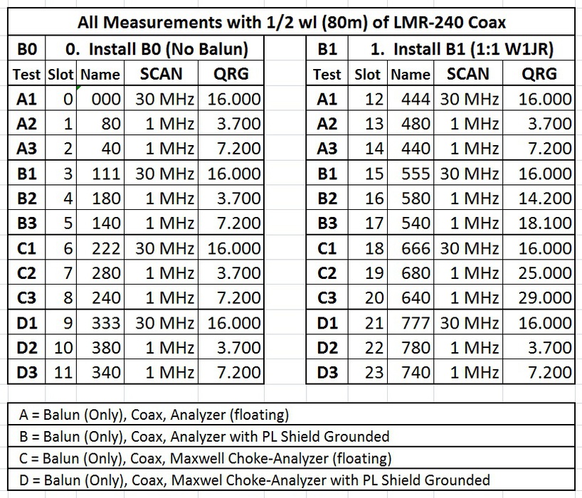
The table on the left shows how I measured and recorded each of the twelve measurements for B0, the one on the right is identical, except using a different balun (B1).
The Comprehensive Tests
I will explain the comprehensive tests in detail on the page "Comprehensive Analysis."

N E W

A Short Video by W8JI
N E W
OCFD ANTENNA
PRESENTATION


( Info-Only; NO SALES! )
Spiderbeam on Facebook:


BRAND NEW
from Spiderbeam:

Mini "SOTA" Pole
by Rob Sherwood NC0B

(AUF DEUTSCH)


Spiderbeam FG Pole

Photo: Nischal Nethrananda

A fun film about
Ham Radio Outdoors
(not just in Tenerife)
(English & German)


(nearly) Invisible Pole

An Aerial-51
Sponsored Expedition:
INTRODUCING
Special purpose Aerials:

Ultra-Lightweight antennas for expeditions and stealth applications.
+
(other)
---------------------
UPDATES:
|
|
-----------------
LL-TUNER "S-MATCH"
added to my
symmetrical tuner page.
----------------------
PROGRESSING:
LOTS OF NEW CONTENT IN THE SECTION:


Since JAN-2013
*******************