
Battle of Baluns FINDINGS:
THIS PAGE will present findings of my examination of the data.
The order of listing on this page in not significant.
I am simply storing my findings here as I find them.
I will sometimes make a couple of comments, but the final conclusion cannot be drawn until after much of the data has been analyzed in detail. This will definitely take a while!
NOTE: These are only my "FINDINGS", NOT my "CONCLUSIONS" !!!
PRELIMINARY TEST FINDINGS:
GROUNDING at the ANALYZER:
The first thing I did with each balun was perform a “Preliminary Test”, with an electrical half wavelength of coax and 4 configurations:
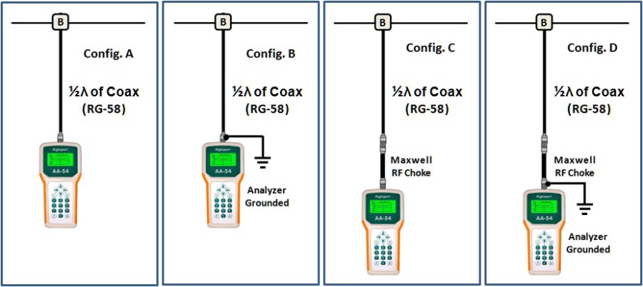
I was interested in finding the affect that grounding had at two frequencies:
- Frequency and SWR Level @ SWRmin
- (the frequency at which minimum SWR occured)
- Frequency and SWR Level @ j0
- (the actual frequency of resonance)
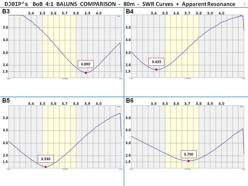
If we compare a bad Balun (“B3” Model 4115) with a good Balun (“B4” DJ0IP Hybrid), and then compare the SWR data for ungrounded vs. grounded (@SWRmin):
- B3: 1.47 @ 3.750 MHz ¦ 1.16 @ 3.670 MHz (significant change)
- B4: 1.53 @ 3.440 MHz ¦ 1.53 @ 3.440 MHz (no change)
And, if we compare a bad Balun (“B3” Model 4115) with a good Balun (“B4” DJ0IP Hybrid), and then compare the SWR data for ungrounded vs. grounded (@j0):
- B3: 1.56 @ 3.670 MHz ¦ 1.19 @ 3.640 MHz (significant change)
- B4: 1.53 @ 3.435 MHz ¦ 1.53 @ 3.435 MHz (no change)
CONCLUSION:
If you have a good balun, the ground makes no difference.
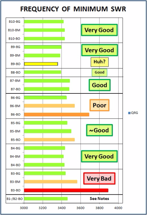
APPARENT RESONANCE: "AR"
AR = Frequency of Minimum SWR . . . "SWRmin"
AR: This is a term which I have created to indicate the point of minimum SWR on any measurement. This is rarely the true point of resonance!
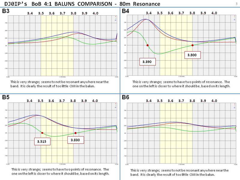
True resonance is the point where:
Capacitive Reactance = Inductive Reactance and their sum is ZERO
and the antenna is purely Resistive.
It is common amonst hams to speak of the point of minimum SWR as being the point of resonance. In the case of a dipole it is usually close to being true resonance, but it rarely exactly the same frequency.
In the case of Off Center Fed Dipoles (OCFD), Common Mode Current (CMC) is a significant problem that skews SWR readings so badly that it is simply wrong to ever use the term "resonant". We should use the term Apparent Resonance (AR), to be sure people don't believe it is actually true resonance. Even better is to call it the frequency of minimum SWR (SWRmin).
The table below shows how the "AR" varies, depending on the configuration:

I failed to complete the tests in 2015 before the winter set in.
B4 was considered the leader at the end of the year.
When I returned to the field in 2016, I began by re-testing B4 to make sure nothing at the QTH or its surroundings had changed that would skew the test results.
Therefore B4 is shown twice in the charts.
NOTES:
NT = Not Tested
In the case of B0 thru B2, it made no sense to test these. B6 and B4 were tested early in the tests, before I had decided to run a thorough BoB. When I later defined BoB, I opted to also test 40m with the extended coax.
Baluns B1 and B2 are 1:1 baluns and no attempt was made to match their impedance to that of the antenna. These are actually just 1:1 Guanella Chokes (choke baluns). On some of the higher bands the mismatch is pretty high, so I only showed the 80m band.
Balun B0 is of course not even a balun. It is just an insulator with an SO-239 for connecting wires directly to the coax. I tested it like the others because I wanted to know what it would look like in an OCFD. I have never seen anyone test and report this before. It looks like CRAP, but at least now we know and don't have to guess! (hi)
Baluns B4 thru B7 are all 4:1 baluns.
- B4 is a hybrid balun consisting of a 4:1 Ruthroff (voltage) balun used only as a transformer, combined with a 1:1 Guanella (choke balun), similar to B1 above.
- All other baluns are Dual-Core Guanella baluns.
VERY IMPORTANT: This table only shows the ability of the different baluns to impeed CMC when measured with a low signal level coming from an analyzer. There are SIGNIFICANT DIFFERENCES in the POWER HANDLING ABILITY of these different baluns.
REMEMBER: This table is showing "Apparent Resonance", not true Resonance.
COMMENTS:
In an ideal case, there would be no Common Mode Current (CMC) at all, and therefore the AR would be the same whether an RF choke was added to the feedpoint or not. In fact adding more coax would only affect the SWR reading, not the AR.
If the antenna were perfectly matched to the 50 Ohm coax, the addition of 20 ft. of coax would make no difference at all in the AR. It would only affect the level of SWR.
Unfortunately we have CMC present in all cases, and in most cases it is quite severe!
Adding 20 ft. of coax can make a significant difference in AR as well as level of SWR, because the level of CMC is not equal along the coax. It varies significantly as the length of coax varies, being minimum at approximately 1/4 wavelength and maximum at approximately 1/2 wavelength away from the feedpoint.
Of course if the CMC is very low, the change in AR by adding more coax will be low.
Conversely, if the change in AR due to adding more coax is significant, then there is a significant amount of CMC on the line.
- GOOD BALUN: All measured AR's are nearly the same.
- BAD BALUN: The AR varies significantly depending on the configuration.
THE MEASURED RESULTS ARE SHOWN IN THE TABLE.
Please study them and draw your own conclusions.
"PRELIMINARY" CONCLUSIONS:
- All baluns in this test appear to be good enough, provided we use a very good (Guanella) RF Choke with them. In some cases even the Maxwell is enough.
- Some of the baluns, even commercial ones thought to be good baluns, fail miserably to provide enough Common Mode Impedance (CMI) to keep CMC off of the feedline.
- In this initial evaluation of only 80 and 40m, B4 was the clear winner - by far! This may change after I have carefully evaluated the higher bands.
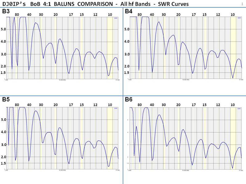
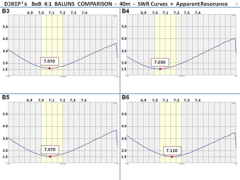
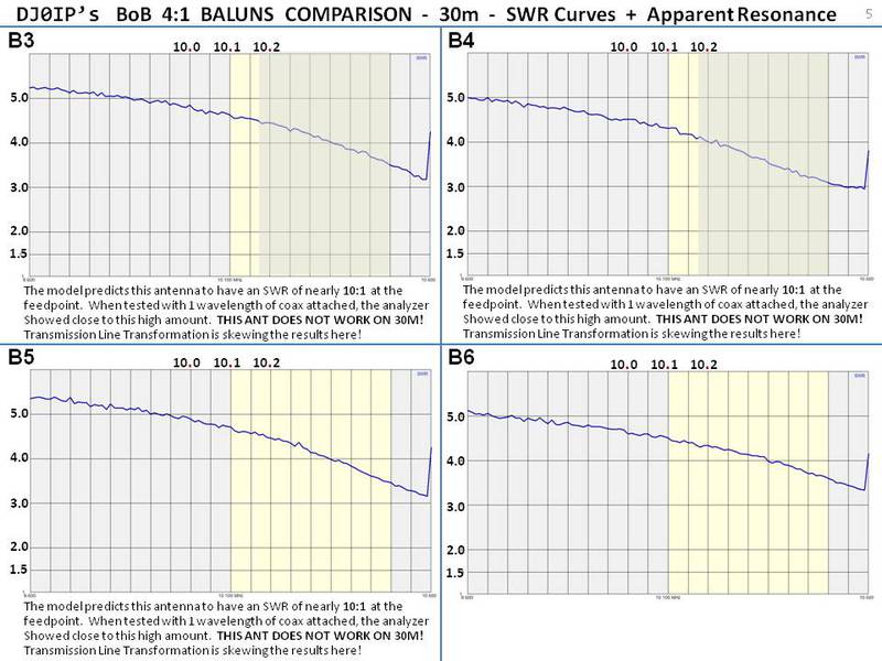
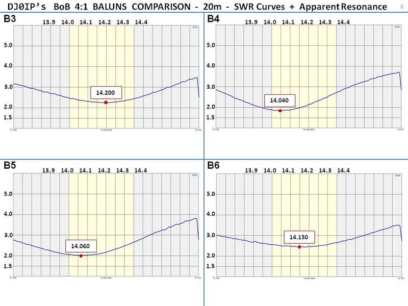
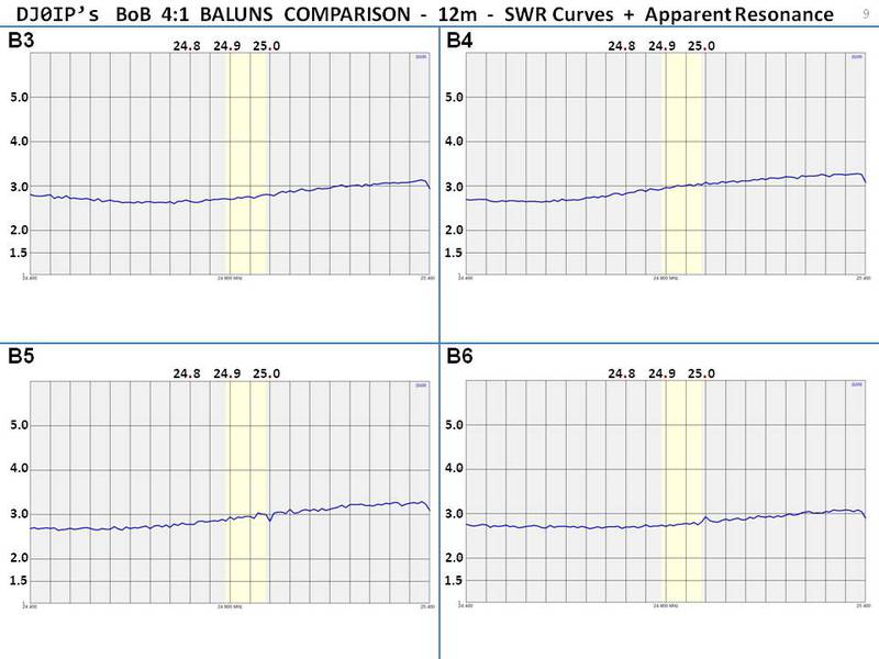
ALL HF BANDS, BALUN ONLY
The gallery below contains a slide for each band, comparing the 4 baluns' SWR curves. No additional choke was attached. ALL baluns were attached to the same set of wires, using the same 15m of RG-174 HCU coax.
NOTE: The approximate antenna overall length is 133.5 ft. or 40.70m. Using the formula 468/f, the calculated resonant frequency should be right at 3.500 MHz.
When I measured resonance using a 1:1 Guanella choke (only) at the feedpoint, I determined resonance to be 3.460 MHz with both B1 and B2. Interesting, B4 also showed this frequency.
I will try to build and measure one more balun before winter, then I will take down the antenna and measure its length exactly. It should be within plus/minus 10 cm (4 in.) of the value shown here. I will update this section once I have measured the antenna.


D I S C U S S I O N :
The collection of data above is enough to draw some basic "preliminary" conclusions, but CAUTION! This is just a fraction of the data available on these baluns. Without viewing all the data, it would be easy to draw some FALSE CONCLUSIONS!
A picture is worth 1000 words:
NOTES:
B1 and B2 are very similar 1:1 Guanella chokes, using the same size toroid, but with different ferrite mixes (#43 & #31). Both have very high CMI (ca. 8 kOhms on 80m). It is presumed that the frequency they both show minimum SWR is the point of minimum SWR, or "Apparent Resonance". Don't forget, this is not exactly true resonance, but it is close.
B8 "looks" peculiar. It shows resonance too low. This test was conducted 3 months before any of the other test and I only made a couple of measurements. I did not run the complete test suite. I don't want to draw any false conclusions, so I will postpone any comments until after I have run the full suite of tests on it...which may be next year (2016).
GOODNESS is when the apparent resonance of the balon alone ("BO") is the same or at least nearly the same as it is when used together with a choke, AND matches the AR shown with B1 and B2.
WINNERS:
- B4 appears to be the clear winner,
- B10, basically the same circuit, just smaller cores, is also the co-winner.
- B9 may also be a co-winner but the drop in resonant frequency is curious.
- but B7 was not far behind. The results would be clearer if I had managed to test B7 with a 1:1 Guanella choke, but that didn't happen.
Remember, B1 and B2 do not transform the impedance, so they are only good on the lower bands.
- B4 = Hybrid Balun with 4:1 Ruthroff (FT-240-61) and 1:1 Guanella (FT-240-43)
- B7 = Dual-Core 4:1 Guanella Balun with 2x FT-240-43 toroids.
- B9 = K6KBE's CBC Balun
- B10 = Mini Hybrid Balun
DISCUSSION ________________________________________________

N E W

A Short Video by W8JI
N E W
OCFD ANTENNA
PRESENTATION


( Info-Only; NO SALES! )
Spiderbeam on Facebook:


BRAND NEW
from Spiderbeam:

Mini "SOTA" Pole
by Rob Sherwood NC0B

(AUF DEUTSCH)


Spiderbeam FG Pole

Photo: Nischal Nethrananda

A fun film about
Ham Radio Outdoors
(not just in Tenerife)
(English & German)


(nearly) Invisible Pole

An Aerial-51
Sponsored Expedition:
INTRODUCING
Special purpose Aerials:

Ultra-Lightweight antennas for expeditions and stealth applications.
+
(other)
---------------------
UPDATES:
|
|
-----------------
LL-TUNER "S-MATCH"
added to my
symmetrical tuner page.
----------------------
PROGRESSING:
LOTS OF NEW CONTENT IN THE SECTION:


Since JAN-2013
*******************