
COMPONENTS
The Antenna

The Antenna is an 80m OCFD, approximately 40,70m long, with a feedpoint split of 29.6%.
The wire used was WIREMAN CQ-534, AWG-26 insulated, stranded CopperWeld.
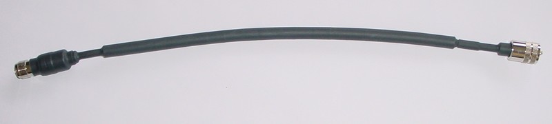
For most tests, an exact half wavelength of brand new RG-58 coax was used. On a couple of the tests I used foam coax instead, but it too was a half wavelength long.
The feedpoint is mounted about 12.5m up an 18m Spiderbeam telescoping fiberglass pole and the antenna was hoisted up and down via a pulley near the top.
The same wires were used throughout the test. The balun was swapped (B1 thru B12). In addition and just for fun, I tested the wires with B0, which was a straight connection to an SO-239.
The long end is about 6m high and the short end is about 8m high.
In the picture, the long end runs away from the viewer, the short end runs towards the viewer.
The nearest house is about 400m (about a quarter mile) away.
The Baluns
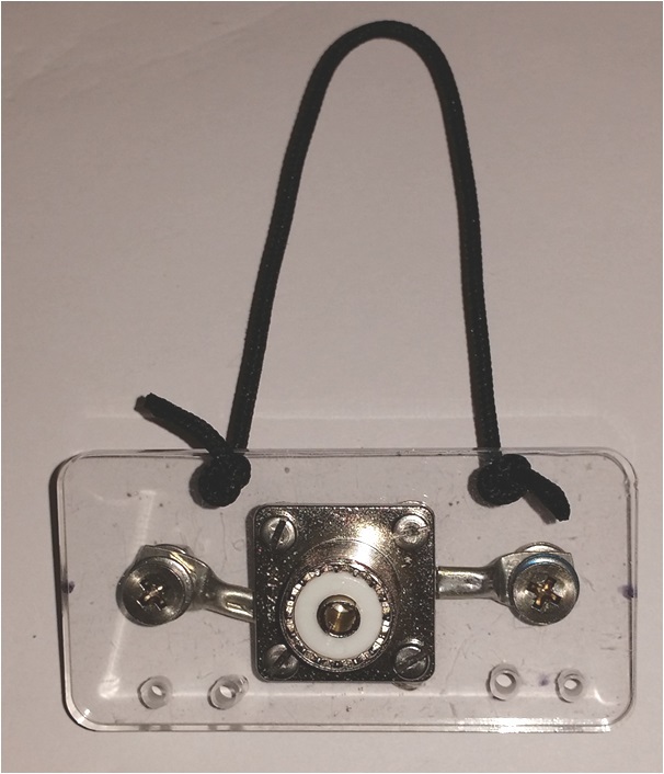
B0: No Balun at all.
An SO-239 coax jack was mounted on a piece of plexiglass with screw attachment for attaching the two legs of the OCFD antenna. 2 holes per side provide the strain-relief.
A short loop of Kevlar rope was provided for connecting to the main rope.
I had no idea what to expect, but I thought as long as I have everything prepaired, let's just see what it looks like without a balun.
The results were ugly; real ugly!
(It is no longer on my bucket list.)
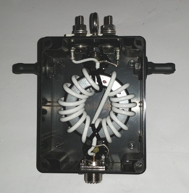
B1: 1:1 Guanella (W1JR) Balun
The balun consists of 17 turns of special Teflon Coax, similar to RG-142, wound onto an FT-240-43 toroid core.
This coax is much more flexible than RG-142, making it much easier to work with, but it cannot handle as much power as RG-142. However it is good for one kW or better so it was more than good enough.
According to the chart on G3TXQ's web page, this balun exhibits the following CMI characterics:
- 80/40m 8 kOhm
- 30/20m 4 kOhm
- 17/15m 2 kOhm
- 12/10m >1 kOhm
The "ears" on the left and right side are stainless steel bolts, floating, covered with heat-shrink tubing. These will be used to provide the strain-relief for the antenna legs.
The wires connect on the top of the balun, left and right of the eye-bolt.
This, B0 and B8 were the only baluns I tested using RG8X foam coax.
All other tests used RG-58.
B2: 1:1 Guanella (W1JR) Choke Balun
This choke balun consists of :
- 1.40m (4'7") of special Teflon-like Coax (DXW142), similar to RG-142
- with 17 turns cross-wound (W1JR)
- onto an Amidon FT-240-31 toroid core.
- 2x PL-259 with gold-plated contacts and Teflon insulation.
DXW142 FEP/TPE-U coax cable 50 Ω
Specifications:
Inner conductor material : solid copper, tinned
Inner conductor diameter: 0.98 mm
Dielectric: FEP, 3.02 mm
Power handling (estimated) : 4KW @ 10MHz ; 2KW @ 30MHz
The inner conductor is made of solid copper ( better thermal conductivity
than the Copperweld steel wire in RG142B/U).  By tinning, FEP was used
as a dielectric, since only silver plated wires can be extruded with PTFE.
FEP nearly reaches the properties of PTFE
According to the chart on G3TXQ's web page, this balun exhibits the following CMI characteristics:
- 160m > 4 kOhm
- 80m 8 kOhm
- 40m 4 kOhm
- 30/20/17m 2 kOhm
- 15/12/10m >1 kOhm
This was the first balun tested where I used the single half wavelength long piece of RG-58 coax. I used the analyzer to confirm that it was indeed exactly 1/2 wavelength long on 3.480 MHz.

B3: Balun Designs Model 4115t (modified)
- This is the standard Model 4115t balun with top mounted connection bolts.
- I have added two bolts, one on each side, to be used for strain relief purposes.
- The bolts do not connect to anything inside the balun.
- There were no changes made to the electrical characteristics of the balun.
B3 SWR CURVES:

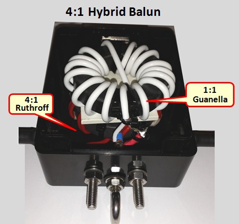
B4: Hybrid Balun (4:1 Ruthroff + 1:1 W1JR)
This Balun consists of a 4:1 Ruthroff Balun on the antenna side, preceded by a 1:1 Guanella Balun on the coax side.
- The 1:1 Guanella Balun is the same Balun as used in "B1" above.
- The 4:1 Ruthroff is wound on an FT-240-61 Core.
- The enclosure is a standard Spiderbeam balun enclosure.
In this case, the Ruthroff is used as an impedance transformer and the Guanella performs the duty of impeding Common Mode Current.
Neither balun on its own is sufficient to match impedance and impede Common Mode Current.
B4 SWR CURVES:
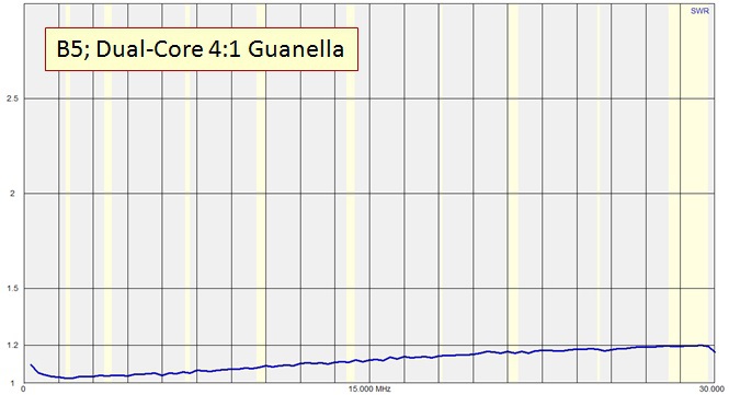
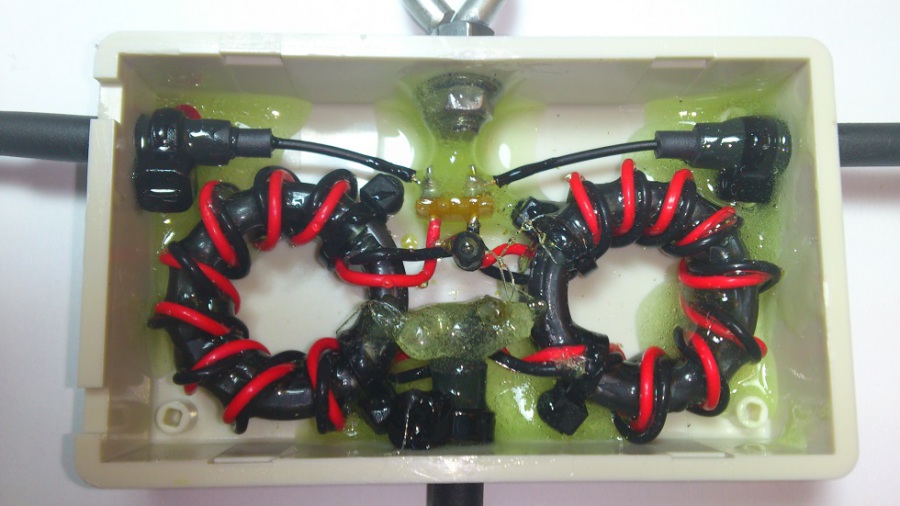
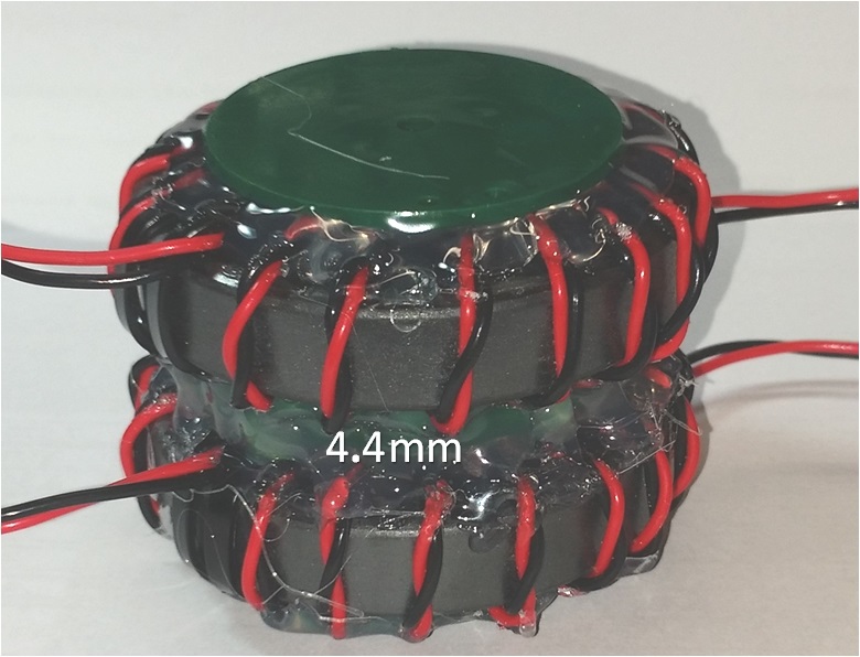
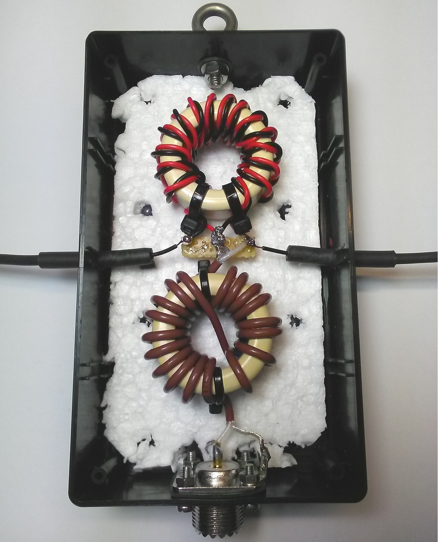
B5: Dual-Core 4:1 Guanella Balun
Consisting of 2x Ferroxcube TX 36/23/15-4A11. These cores are nearly identical to FT-140-43, except these have a thin epoxy coating on the outside surface. Their beginning permeability is 850.
I wound each toroid with 12 turns of twisted pari, Teflon insulated 0,75 sq. mm wire. This is in between AWG18 and AWG19.
After winding 12 turns of wire on each core and coating them with black "Plasti Dip", their inductance was 129.2 uH and 131.5 uH, which is a tolerance of 1.8%. This is close enough to call them a matched pair of toroids.
Note: The picture above on the right is of my 40m balun. The 80m version uses 2 more turns of wire, but otherwise looks exactly like that. It is shown in the gallery below.
Note: The SO-239 is Teflon insulated, gold plated (top quality).
All solder joints are insulated with heat-shrink tubing with hot glue inside. The balun is perfectly water-proof, even though it is open frame. Of course you need to wrap the coax connector with tape or other weather proofing material.
GALLERY:
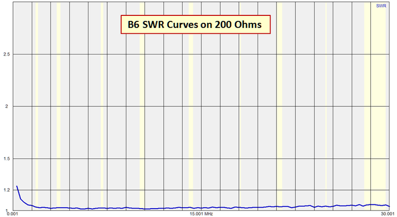
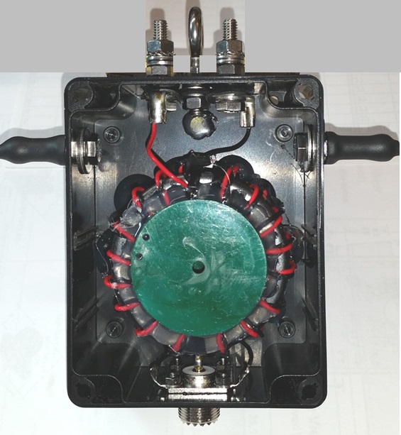
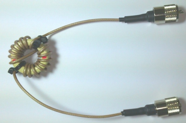
B6: Dual-Core 4:1 Guanella Balun
Consisting of 2x Ferroxcube CST 29/19/7.5-4S2. These toroids are nearly identical with FT-114-43 (beginning permeability of 850).
Each core is wound with 10 turns of twisted pair, Teflon Insulated, 0.75mm wire.
Note: The picture on the right shows my 40m version of this balun with just 10 turns. The 80m version is exactly the same, but with 12 turns.
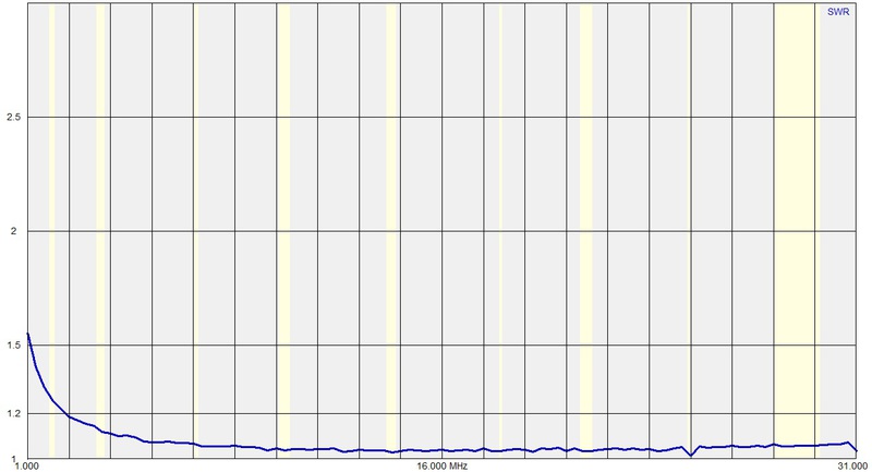
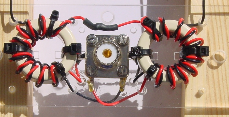
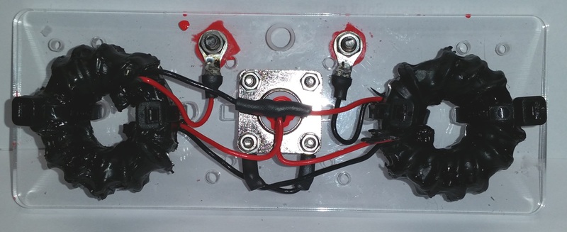
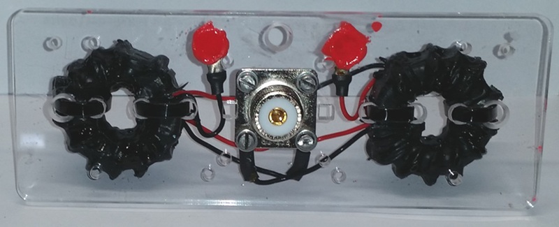
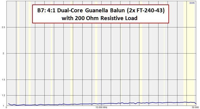
 B7 Dual 2.4 in. 4:1 Guanella Balun
B7: Dual-Core 4:1 Guanella Balun
This larger balun uses:
- 2x FT-240-43 Toroies
- 17 turns cross-wound in W1JR crossover fashion
- 0.75 sq. mm. Teflon-Insulated wire
- Weight: 580 grams (abt. 20 oz.)
- A standard Spiderbeam balun enclosure
B7 SWR Curves and other Pictures:
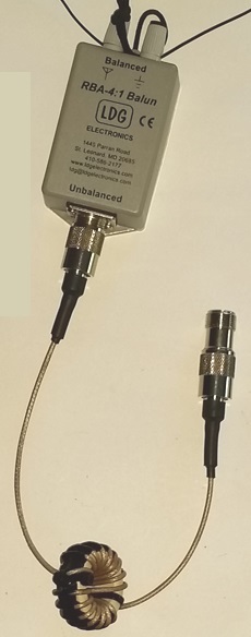
B8: Tiny Hybrid Balun
This 2-Core Balun consists of:
- an LDG LBA-4, 4:1 Ruthroff Balun
- a 1:1 Guanella Choke (see below)
This balun was thrown together for a quick test in the early stages of my 80m OCFD research. At that time I did not yet know that I would do the Battle of Baluns test, so I did not perform the entire suite of tests. However I did record enough measurements to give us meaningful and interesting results.
As we've known since Roy Lewallen's (W7EL) work with baluns as documented in his 1985 paper, "Baluns: What They Do and How They Do It", the Ruthroff (voltage) balun is very poor at suppressing Common Mode Current. Used in an OCFD antenna it is more or less worthless. But as we will see here, when combined together with a 1:1 Guanella Choke (Balun), it makes a fairly good combination - called "Hybrid Balun."
Unfortunately this LDG balun is not waterproof and its screws are not stainless steel, so it quickly rusted during my tests.
Never-the-less, the test results are very interesting, and will be shown here as an additional data point on the topic of baluns for 80m OCFD antennas.
As a result of these meausrements, I decided to investigate several other balun technologies.
This led to the idea of a "Battle of Baluns."
B9: Special CBC
- Weight: 223 gr.
Sorry, no further details about this balun technology are available at this time.
This is proprietary information of Mel, K6KBE.
Contact info is in QRZ.com.

B10: Small Hybrid Balun
- 4:1 Ruthroff and 1:1 Guanella
- Weight: just 116 gr. (!)
RUTHROFF:
- 1x FT-114-61 Toroid
- 14 turns of twisted pair wire
- Wire: 0.75 sq.mm. Teflon insulated (abt. 18-AWG)
GUANELLA:
- 2x FT-114-43 (glued together)
- 17 turns of RG-178 Teflon insulated coax
B10 SWR CURVES:


B11 Medium Size Hybrid Balun
- 4:1 Ruthroff and 1:1 Guanella
- Weight: __ g
RUTHROFF:
- Ferroxcube TX36/23/15-4C65 (similar to an Amidon FT-140-61).
- 15 turns DX-W Twisted Pair Teflon insulated, silver-plated wire, 0,75 qmm.
GUANELLA:
- Ferroxcube TX36/23/15-4A11 (similar to an Amidon FT-140-43).
- 19 turns DXW188 (RG-316) Teflon insulated coax
The test results for B11 are not yet uploaded but they are good and about the same as B4 and B10.
You can view the SWR curves of this balun used in an 80m OCFD on the Aerial-51 web site:
https://www.aerial-51.com/model-807-xx/
B11 SWR Curves:


INTERESTING: Looking at the second picture, the middle, we see that even just 8cm of RG-174 with a 50 Ohm resistor rises from1.02:1 (on 160m) to 1.1:1 (on 10m).
When we then connect the 1:1 Guanella between the coax and the analyzer, 160m is still 1.02:1 and 10m then rises to 1.2:1.
B12 Protype Hybrid Balun for 807-L
- Electrically this balun is identical to B11 above.
- The production unit will be in a plastic enclosure.
- The enclosure will be potted with 2-component epoxy.
- The styrofoam is only to reduce volume of epoxy required, thus reducing weight.
NOTE: These antennas are built and sold by Spiderbeam GmbH, a German company.
Aerial-51 does not sell anything.
Currently no further baluns are forseen for this test.
The RF Chokes:
The Maxwell Choke
The RF Choke used at the analyzer was a simple home-brew Maxwell, consisting of 20 ferrite beads, type Ferroxcube 9.5-5.1-15-3S4. These beads have a beginning permeability of 1700.
The CMI of this choke is about 1000 Ohms.
This choke was used at the analyzer on all Bx-BO and Bx-BM tests and specific Bx-BOL tests.
This type of choke was also used at the feedpoint during all Bx-BM comprehensive tests, together with the various baluns.
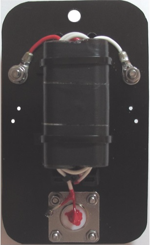
The Guanella Choke
This choke uses 16 turns of RG-316 Teflon Coax, cross-wound using the W1JR method. The core is a Ferroxcube TX36/23/15-4A11, which is similar to an FT-140-43. This Ferroxcube toroid has a thin layer of epoxy on its surface, making it suitable for outdoor use.
This choke was not used in the preliminary tests, but was used at the feedpoint in addition to the various baluns, during all Bx-BG comprehensive tests.

N E W

A Short Video by W8JI
N E W
OCFD ANTENNA
PRESENTATION


( Info-Only; NO SALES! )
Spiderbeam on Facebook:


BRAND NEW
from Spiderbeam:

Mini "SOTA" Pole
by Rob Sherwood NC0B

(AUF DEUTSCH)


Spiderbeam FG Pole

Photo: Nischal Nethrananda

A fun film about
Ham Radio Outdoors
(not just in Tenerife)
(English & German)


(nearly) Invisible Pole

An Aerial-51
Sponsored Expedition:
INTRODUCING
Special purpose Aerials:

Ultra-Lightweight antennas for expeditions and stealth applications.
+
(other)
---------------------
UPDATES:
|
|
-----------------
LL-TUNER "S-MATCH"
added to my
symmetrical tuner page.
----------------------
PROGRESSING:
LOTS OF NEW CONTENT IN THE SECTION:


Since JAN-2013
*******************