
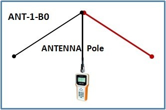
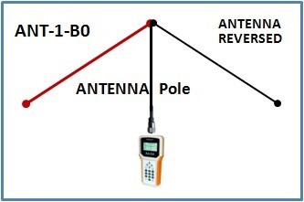
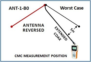
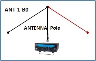
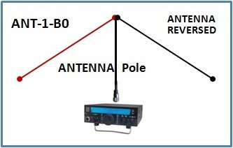
TEST RESULTS DATA: ANT-1-B0
A SIMPLE DIPOLE, NO BALUN, NO CHOKE
(Tested Here: Inverted-V
configuration)
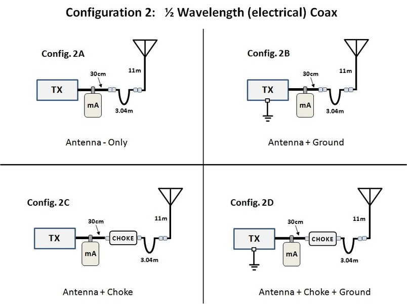
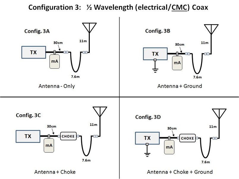
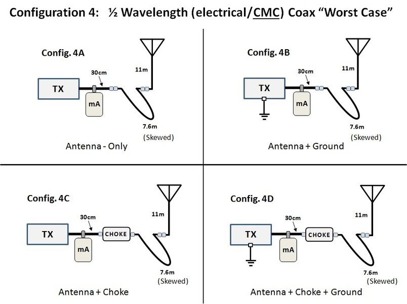
GENERAL TEST CONFIGURATIONS:
(click on picture)
ANTENNA ANTENNA ROTATED WORST CASE (WC) WC ROTATED

SPECIFIC TEST CONFIGURATIONS:
(click on picture)
BASIC ANT COAX λ/2 (el.) COAX λ/2 (cmc) COAX λ/2 (cmc)WC
NOTE:
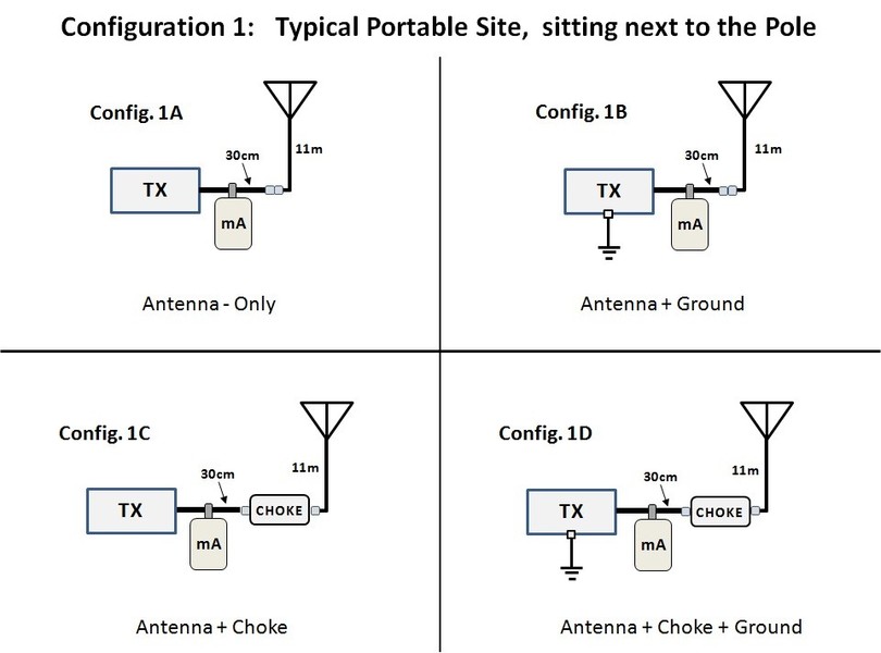
- The pictures above show the 16 configurations with a transmitter attached. This is the setup for the CMC measurements.
- For the SWR and other basic antenna characteristics test, an Antenna Analyzer was used instead of the transmitter.
- Both versions of these pictures are available as a PDF, BELOW:
This file shows larger pictures and includes the name(s) of the specific coax used in each test.
BASIC SWR TEST CONFIGURATIONS.pdf
PDF-Dokument [448.6 KB]
Thsi file shows larger pictures and includes the name(s) of the specific coax used in each test.
BASIC CMC TEST CONFIGURATIONS.pdf
PDF-Dokument [426.0 KB]
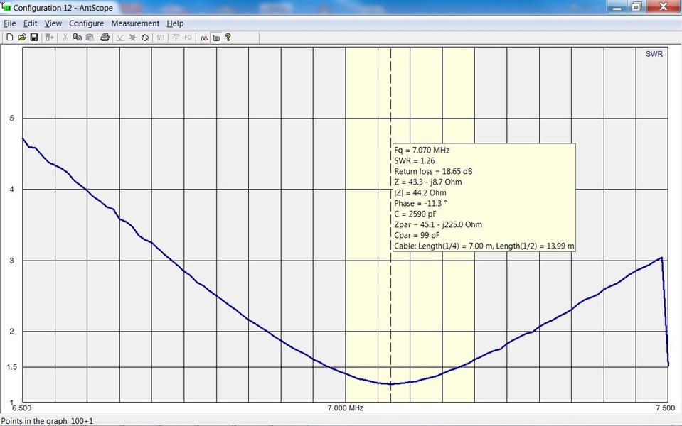
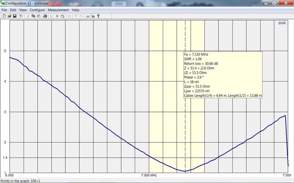
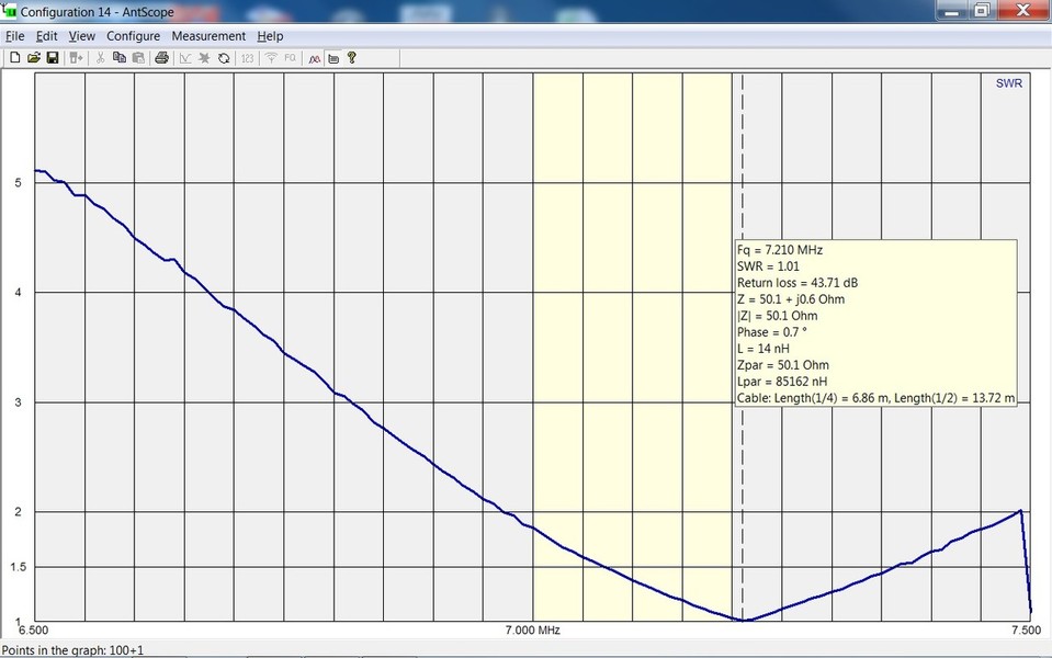
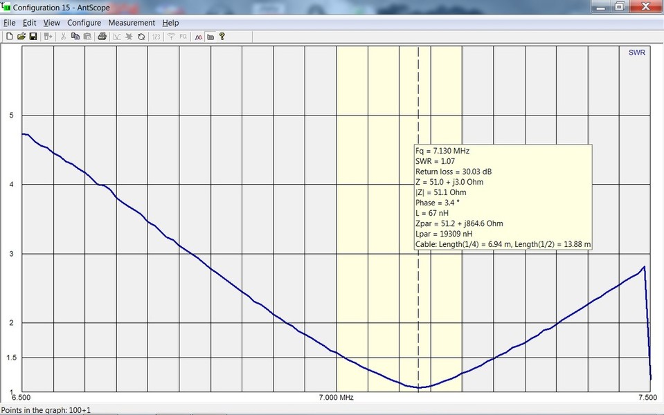
BASIC CHARACTERISTICS:
SWR Curves measured with a RigExpert AA-54:
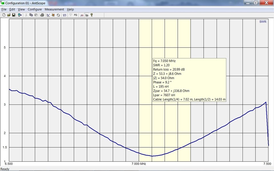
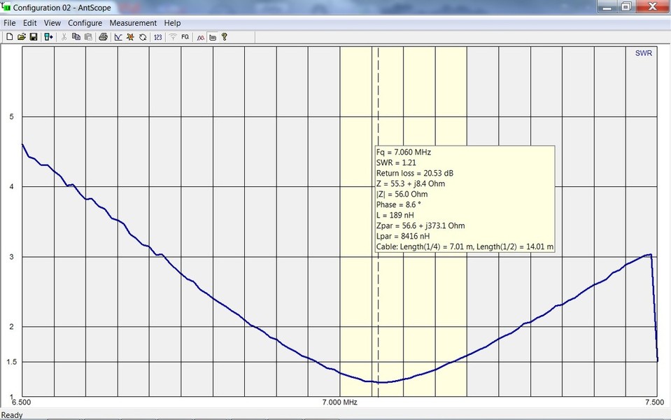
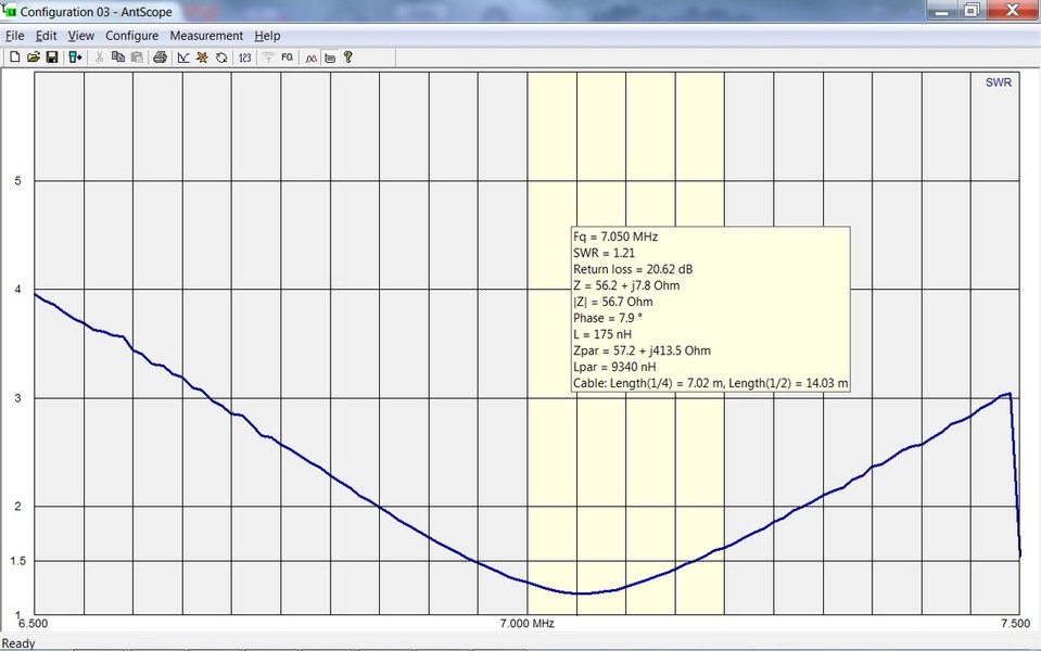
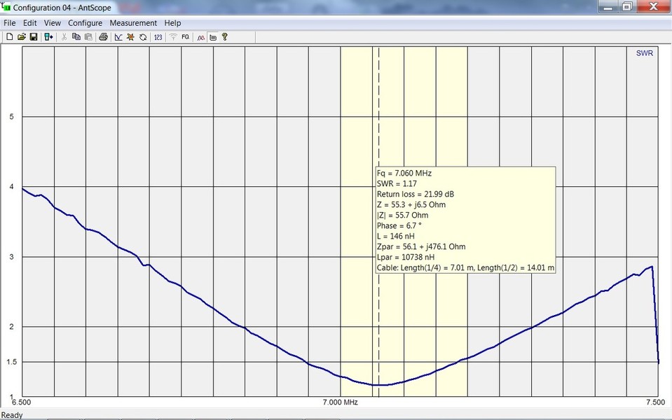

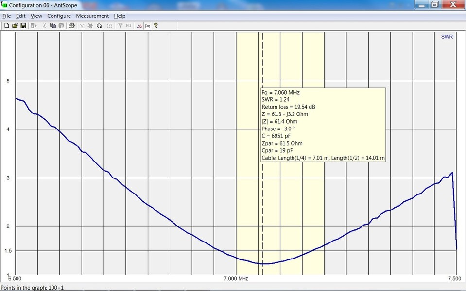
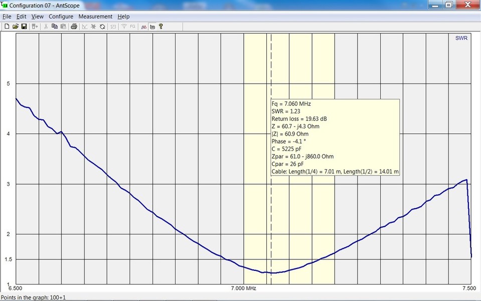
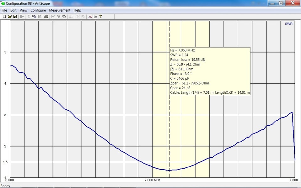
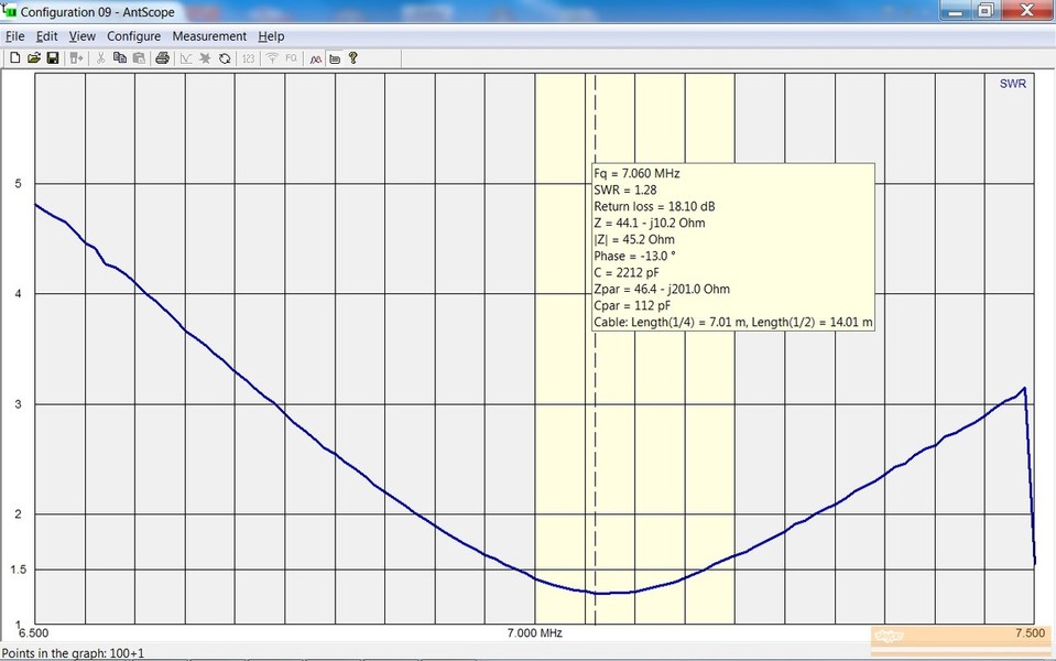
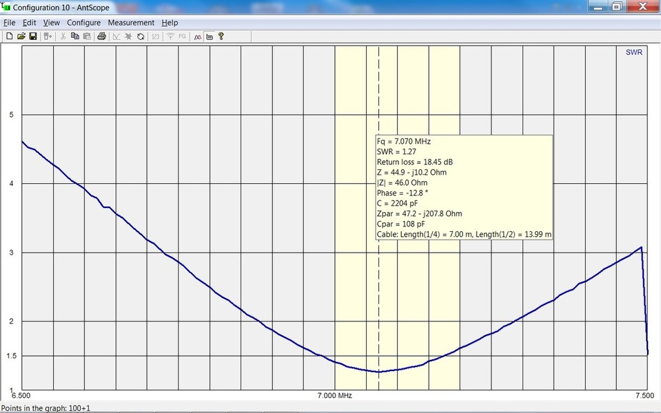

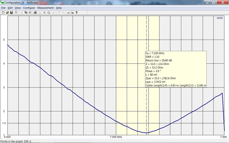
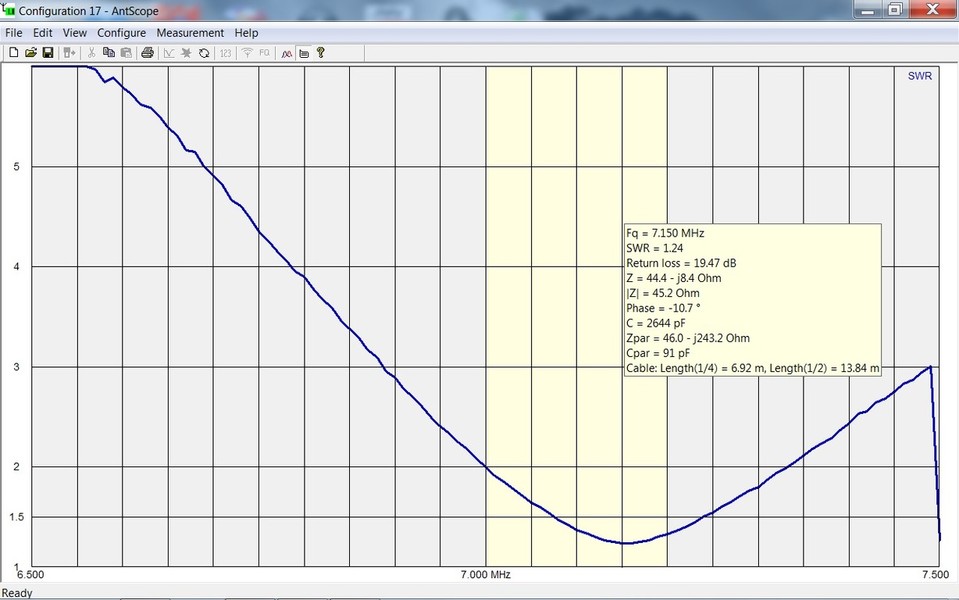

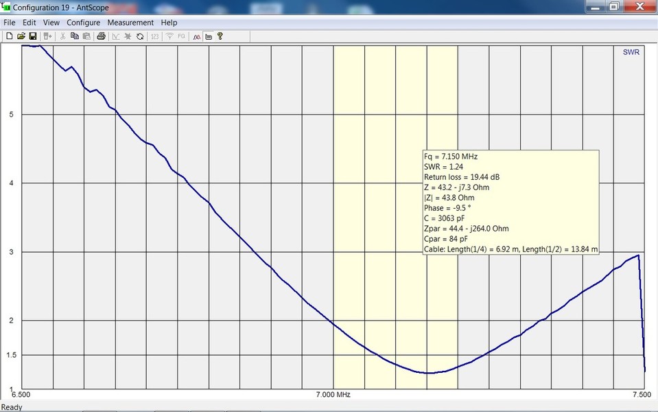
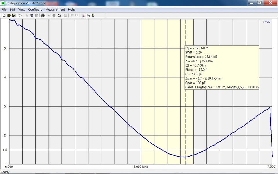
ANALYZER DATA:
Here are the original data files, as measured on a RigExpert AA-54.
To view these files, download (free) ANTscope and after installing and opening, don't forget the select the analyzer type (AA-54).
Antenna Characteristics.zip
Archivdatei im ZIP Format [2.0 MB]
Viewing Analyzer Data on YOUR computer:
You can view ALL of the data measured by the analyzer on your own computer.
For instructions on how to do this, see: Viewing Analyzer Data
MEASURED COMMON-MODE-CURRENT
TEST CONFIGURATIONS:
(click on picture)
ANTENNA ANTENNA ROTATED WORST CASE (WC) WC ROTATED

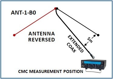
The measured CMC results while running 100w into this antenna are shown in the file below.
This is an Excel spreadsheet showing results of the CMC measurements on ANT-1-B0. The file format is Office 2007 version of Excel (.xlsx)
CMC-TEST RESULTS ANT-1-B0.xlsx
Microsoft Excel-Dokument [105.5 KB]
This is a PDF version of the Excel spreadsheet. It is the same as the Excel file above.
CMC-TEST RESULTS ANT-1-B0.pdf
PDF-Dokument [203.4 KB]
NOTE: When I ran the initial set of tests on ANT-1-B0, I took each measurement on two different settings of the RF Ammeter:
- Full Scale 300 mA
- Full Scale 100 mA
The 100 mA is an "amplified" reading, meaning the signal is amplified.
The 300 mA scale is not amplified. It reads directly to the meter.
As you see in the results, the measured values were always different.
My gut feeling is, the non-amplified scale is more accurate than the amplified scale.
REALITY: IT DOES NOT MATTER.
REASON: At very low values where you need the amplified scale, the amount of CMC is so low that it causes no impact to the antenna.
ANT-1-B0 RESONANCE TEST
THE POINT OF MINIMUM SWR.= RESONANCE ...WRONG!
This is a common misconception!
Of course it is generally pretty close to the point of resonance
but it is never exactly the same point,
ESPECIALLY IN THE PRESENCE OF COMMON MODE CURRENT!
The file below shows the measured resonance of the antenna when measured:
- With the analyzer alone.
- With the analyzer grounded.
- With an RF Choke in the line, NO ground.
- With an RF Choke in the line, AND the analyzer grounded.

N E W

A Short Video by W8JI
N E W
OCFD ANTENNA
PRESENTATION


( Info-Only; NO SALES! )
Spiderbeam on Facebook:


BRAND NEW
from Spiderbeam:

Mini "SOTA" Pole
by Rob Sherwood NC0B

(AUF DEUTSCH)


Spiderbeam FG Pole

Photo: Nischal Nethrananda

A fun film about
Ham Radio Outdoors
(not just in Tenerife)
(English & German)


(nearly) Invisible Pole

An Aerial-51
Sponsored Expedition:
INTRODUCING
Special purpose Aerials:

Ultra-Lightweight antennas for expeditions and stealth applications.
+
(other)
---------------------
UPDATES:
|
|
-----------------
LL-TUNER "S-MATCH"
added to my
symmetrical tuner page.
----------------------
PROGRESSING:
LOTS OF NEW CONTENT IN THE SECTION:


Since JAN-2013
*******************