
TEST RESULTS DATA: ANT-2-B5
An "OFF-CENTER-FED DIPOLE" with a very modest feedpoint split.
Tested Here:
- Asymmetrical-Inverted-V (A-I-V) Configuration
- 4:1 Guanella Balun, both transmission lines on a single core
- More specific info about this antenna
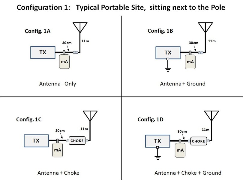
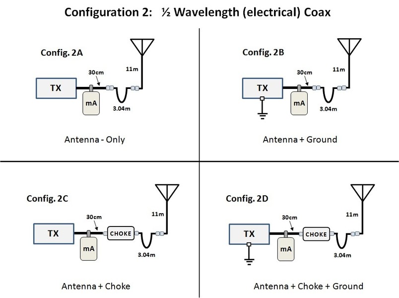
GENERAL TEST CONFIGURATIONS:
.
.
SPECIFIC TEST CONFIGURATIONS:
(click on picture)
BASIC ANT COAX λ/2 (el.) COAX λ/2 (cmc) COAX λ/2 (cmc)WC


NOTE:
- The pictures above show the 16 configurations with a transmitter attached. This is the setup for the CMC measurements.
- For the SWR and other basic antenna characteristics test, an Antenna Analyzer was used instead of the transmitter.
- Both versions of these pictures are available as a PDF, BELOW:
This file shows larger pictures and includes the name(s) of the specific coax used for each test.
BASIC CMC TEST CONFIGURATIONS.pdf
PDF-Dokument [426.0 KB]
This file shows larger pictures and includes the name(s) of the specific coax used in each test.
BASIC SWR TEST CONFIGURATIONS.pdf
PDF-Dokument [448.6 KB]
BASIC CHARACTERISTICS:
SWR Curves measured with a RigExpert AA-54:
NOTE: THERE WERE 128 MEASUREMENTS MADE IN THIS SECTION.
- 88 measurements were made on ANT-2-B5 (normal orientation)
- 40 measurements were made on ANT-2-B5-REV (REVERSED orientation)
- I do not currently have time to convert all of the 128 SWR curves to jpeg photos and upload them.
- Perhaps I will show a few of the more interesting ones when I find time.
ANALYZER DATA:
Here are the original 128 data files, as measured on a RigExpert AA-54.
- "ANT-2-B5"are ALL files measured with the antenna in its "Normal" orientation.
- "ANT-2-B5-REV" are ALL of the files measured at the "Worst Case" operating position, with the antenna in its "Reversed" orietation. Note: no measurements were taken directly at the mast with the coax run perpindicular to the antenna.
These are the 88 analyzer files for ANT-2-B5 with the antenna in "Normal" Orientation. Open with WinZip or WINrar.
ANT-2-B5 Files.zip
Archivdatei im ZIP Format [122.8 KB]
.
These are the 40 analyzer files for ANT-2-B5- REV with the antenna in "REVERSE" Orientation. The antenna was rotated 180 degrees from the "Normal" Orientation. Open with WinZip or WINrar.
ANT-2-B5-REV Files.zip
Archivdatei im ZIP Format [55.8 KB]
MEASURED COMMON-MODE CURRENT
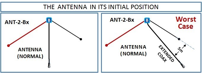
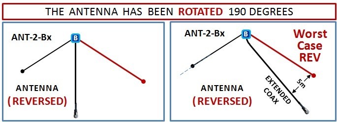
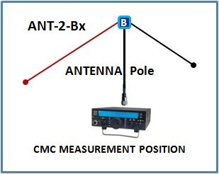
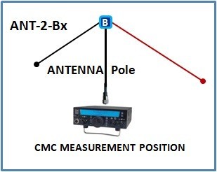
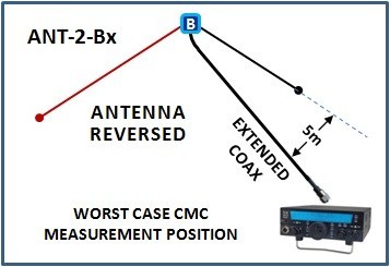
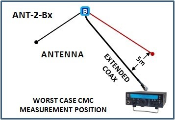
TEST CONFIGURATIONS:
(click on picture)
ANTENNA ANTENNA ROTATED WORST CASE (WC) WC ROTATED
The MEASURED CMC RESULTS while running 100W into this antenna are shown in the file below:
This is an Excel Spreadsheet showing results of the CMC measurements on ANT-1-B0. The file format is Office 2007 version of Excel (.xlsx)
CMC-TEST-Results ANT-2-B5.xlsx
Microsoft Excel-Dokument [17.5 KB]
This is a PDF version of the Excel spreadsheet. It is the same as the Excel file above.
CMC-TEST-Results ANT-2-B5.pdf
PDF-Dokument [79.6 KB]
NOTE: The 16 basic test configurations used here are the same as used all the way through the test. However the "Test Numbers" for testing these OCFD antennas differ from the test numbers used when testing the dipoles. That is because the dipoles were monoband antennas. These OCFD antennas work on 4 bands.
CMC TEST WITH ANTENNA ROATED 180 DEGREES
REVERSED = ROTATED
In my tests, sometimes I refer to this as "reversing the antenna" and sometimes as "rotated antenna". Please assume these mean the same thing through the test.
In all of the drawings, the long leg of the antenna is shownin RED and is connected to the hot terminal of the balun. The short leg is shown in BLACK.
The 88 different test results shown in the files ABOVE were tested with the antenna's:
- long leg to the EAST
- short leg to the WEST
Normally if the antenna were erected in an empty field, free and clear of all objects, and with the coax running at 90 degrees away from the antenna, it would make no difference how the antenna is oriented
The 44 different test results shown in the files BELOW were tested with the antenna's:
- long leg to the WEST
- short leg to the EAST
The difference in CMC between "normal" and "rotated" when measured at the antenna pole was not expected to be significant, so I did not measure the CMC of the rotated antenna at the pole.
Therefore there are only 44 measurements in this section of the test.
HOWEVER, when measureing CMC at the Worst Case position with the coax run nearly parallel to the antenna, I expected there might be significant difference with the antenna rotated. I took these 44 measurements very carefully.
COMPARING "NORMAL" TO "ROTATED"
To make it easier to compare normal tests to rotated or reversed tests, I began numbering the 44 reversed tests with "49" (instead of "01"). This enables us to easily compare tests between normal and reversed.
The file format is Office 2007 version of Excel. (.xlsx)
CMC-TEST-Results ANT-2-B5- Normal vs Rev[...]
Microsoft Excel-Dokument [16.3 KB]
This file is exactly the same as the Excel version above.
CMC-TEST-Results ANT-2-B5- Normal vs Rev[...]
PDF-Dokument [67.8 KB]
INITIAL OBSERVATIONS FROM FROM THE TESTS ON ANT-2-B5
This was the first Off-Center-Fed Dipole that I tested.
Many of the results were as I had expected but there were a few surprises. I also have a few preliminary conclusions which I hope to confirm when I test ANT-3 and ANT-4.
PRELIMINARY CONCLUSION #1:
Whenever more than just a tiny bit of Common Mode Current is present on the coax, it causes skewing of the antenna characteristics. This of course was suspected. The higher the CMC, the more it skewed. Whenever I incountered a large amount of common mode current on the coax (>100mA), the SWR curve of the antenna was skewed dramatically. The analyzer's measurements were sensitive to touching of the coax.
PRELIMINARY CONCLUSION #2:
PRELIMINARY CONCLUSION #3:
The W2DU (Maxwell) RF choke is quite effective as long as the CMC on the line is not too strong. When the coax is run diagonally, quite a ways out of perpindicular to the antenna, this choke is insufficient for reducing the CMC to an acceptable level. A better solution is required. The Reisert-type (Guanella) or GM3SEK-type choke (loops of coax through hunks of ferrite) both reduce the CMC to an acceptable level (0 or very near to 0).
PRELIMINARY CONCLUSION #4:
Although even harmonic frequencies exhibit far less CMC than the that found on the fundamental frequency, the level of the CMC on the odd harmonic frequencies was similar to that of the fundamental frequency. This was totally unexpected. NOTE: I have never seen this reported before, probably because 99% of the OCFD antennas in the world do not function on their odd harmonic bands.
(Mine do!).

N E W

A Short Video by W8JI
N E W
OCFD ANTENNA
PRESENTATION


( Info-Only; NO SALES! )
Spiderbeam on Facebook:


BRAND NEW
from Spiderbeam:

Mini "SOTA" Pole
by Rob Sherwood NC0B

(AUF DEUTSCH)


Spiderbeam FG Pole

Photo: Nischal Nethrananda

A fun film about
Ham Radio Outdoors
(not just in Tenerife)
(English & German)


(nearly) Invisible Pole

An Aerial-51
Sponsored Expedition:
INTRODUCING
Special purpose Aerials:

Ultra-Lightweight antennas for expeditions and stealth applications.
+
(other)
---------------------
UPDATES:
|
|
-----------------
LL-TUNER "S-MATCH"
added to my
symmetrical tuner page.
----------------------
PROGRESSING:
LOTS OF NEW CONTENT IN THE SECTION:


Since JAN-2013
*******************