
I LIKE TO MOVE IT MOVE IT !
PROBLEM: My 80m OCFD antenna has nice resonance on the
harmonic bands but its resonance on 80m is MUCH TOO LOW.
If I shorten the antenna just a little bit on 80m, the harmonic band resonance rises much faster and is quickly our of band.
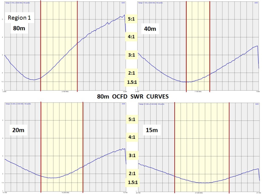
80 / 40 / 20 / 15 Meter Bands:
10 / 30 / 17 / 12 Meter Bands:

Most of the bands above are OK. Most will even work without an antenna matchbox. But 80m resonance needs to move up the band.
NOW THE BIG PROBLEM:
If we look at the exact resonance (actually point of minimum SWR, not resonance), we see that the bands are not exactly harmonically related.

In the chart on the right we see that as we move up in harmonic bands, the resonant frequency (more accurately "point of minimum SWR") skews upwards, higher into the band.
When we try to raise the 80m resonant frequency by shortening the legs of the antenna, we quickly move higher band resonance outside of the band.
Examples with +20 kHz and +40 kHz:
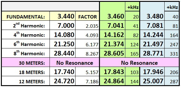
Moving the 80m resonance just 20 kHz up the band already moves harmonic bands resonance considerably, but at least it is still in the band. When we check again after moving 40 kHz up the band (still below the bottom of the 80m band), 15m is already resonant above the band.
AND, basically the 40 kHz change on the 80m band was peanuts.
We can honestly say it did more damage than good.
Obvisously trimming the length of the legs of the 80m OCFD is not the answer! So what is the answer?
THE ANSWER: INSERT A CAPACITOR IN THE LONG LEG
Serge, ON4AA1 has sugested inserting a capacitor at the physical center of the antenna. I have personally conducted field tests and confirmed this to be a good electrical solution.
Others (Andre, DL1ADR2 and Rick, KC8AON) have suggested inserting a capacitor at or inside of the balun at the beginning of the longer leg. From a mechanical standpoint, this is the better solution but I have not yet tested it to see if there are any side affects in doing this.
1 Six Band HF Center-Load Off-Center-Fed Dipole
2 Außermittig gespeiste Dipole
FIELD MEASUREMENTS ON A REAL ANTENNA
I will be brief below but give the reader enough information to study and come to his/her own conclusions.
I went back to the field and made 3 additional sets of measurements on the antenna above.
- 300 pF Capacitor inserted at the middle of the antenna
- 300 pF Capacitor inserted in the long leg, at the balun
- 200 pF Capacitor inserted in the long leg, at the balun
EACH set of measurements includes 11 measurements:
- 30 MHz Scan, center frequency 15 MHz
- 1 MHz Scan, center frequency 3.700 MHz
- 1 MHz Scan, center frequency 7.200 MHz
- 1 MHz Scan, center frequency 10.100 MHz
- 1 MHz Scan, center frequency 14.200 MHz
- 1 MHz Scan, center frequency 18.100 MHz
- 1 MHz Scan, center frequency 21.200 MHz
- 1 MHz Scan, center frequency 24.900 MHz
- 3 MHz Scan, center frequency 29.000 MHz
- 3 MHz Scan, center frequency 50.500 MHz
The files may be viewed with the freeware program "ANTscope"
EXECUTIVE SUMMARY OF THE RESULTS:
(Note: in the interest of simplicity, we will call the point of minimum SWR the "resonant frequency", knowing of course that true resonance (j0) is slightly elsewhere.)
Whereas the capacitor in the center only made significant changes to the fundamental frequency, the capacitor at the balun changes several of the higher bands. This quickly led to problems with higher bands being resonant outside (above) the band.
The picture below shows this trend already beginning on 40m:
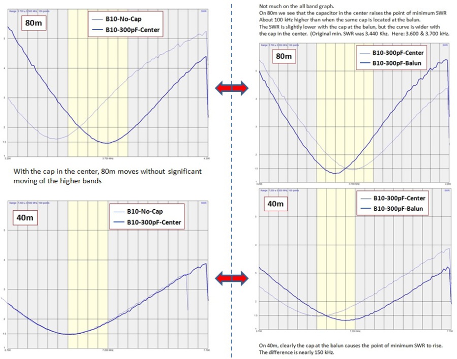
On the left (cap in center) we see significant movement on the fundamental (80m) and nothing at all on 40m.
On the right (cap at balun) we see both bands changing - which is not good. We were only looking to change 80m but unfortunately 40m moves too.
DOWNLOADS OF COMPARISONS:
Comparison before and after inserting a 300 pF capacitor at the center of the antenna.
B10-807-NoCap-vs-300pF-Center.pdf
PDF-Dokument [572.9 KB]
Before and after inserting a 300 pF capacitor at the balun at the beginning of the long leg of the antenna.
B10-807-NoCap-vs-300pF-Balun.pdf
PDF-Dokument [669.1 KB]
Comparison of placing the Cap at the center of the antenna vs. placing it at the balun.
B10-807-300pF-Center-vs-300pF-Balun.pdf
PDF-Dokument [757.9 KB]
Comparison of placing 300 pF vs. 200 pF capacitor at the balun.
B10-807-300pF-vs-200pF-Balun.pdf
PDF-Dokument [752.4 KB]
DOWNLOADS OF DATA FILES:
This is the original antenna without any added capacitance.
2017 B10-O Results.rar
Komprimierte Archivdatei [21.9 KB]
These are the data files with a 300 pF capacitor at the center of the antenna.
C-B10-300pF-CENTER.rar
Komprimierte Archivdatei [21.5 KB]
these are the data files of B10 with a 300 pF capacitor located at the balun.
A-B10-300pF-BALUN.rar
Komprimierte Archivdatei [21.7 KB]
These are the data files with a 200 pF capacitor located at the balun.
B-B10-200pF-BALUN.rar
Komprimierte Archivdatei [21.6 KB]
If, after careful evaluation, anyone should happen to reach a different conclusion than I did, PLEASE CONTACT ME. Thanks.
[END]

N E W

A Short Video by W8JI
N E W
OCFD ANTENNA
PRESENTATION


( Info-Only; NO SALES! )
Spiderbeam on Facebook:


BRAND NEW
from Spiderbeam:

Mini "SOTA" Pole
by Rob Sherwood NC0B

(AUF DEUTSCH)


Spiderbeam FG Pole

Photo: Nischal Nethrananda

A fun film about
Ham Radio Outdoors
(not just in Tenerife)
(English & German)


(nearly) Invisible Pole

An Aerial-51
Sponsored Expedition:
INTRODUCING
Special purpose Aerials:

Ultra-Lightweight antennas for expeditions and stealth applications.
+
(other)
---------------------
UPDATES:
|
|
-----------------
LL-TUNER "S-MATCH"
added to my
symmetrical tuner page.
----------------------
PROGRESSING:
LOTS OF NEW CONTENT IN THE SECTION:


Since JAN-2013
*******************