
D-i-Y: Build an 80m OCFD Antenna
NOTE: I now have a YouTube (2-Part) video on OCFD Antennas.
Part-1 explains the technology and Part-2 shows exactly how to build these, including the balun, as well as how to tune them.
See: https://www.dj0ip.com/hhg2-ocfd
PAGE CONTENTS:
- BACKGROUND & HISTORY
- INTRODUCTION
- PLANNING 'YOUR' OCFD ANTENNA
- BALUN DETAILS
- TUNING THE ANTENNA
- ADJUSTING 80m RESONANCE
1. BACKGROUND & HISTORY
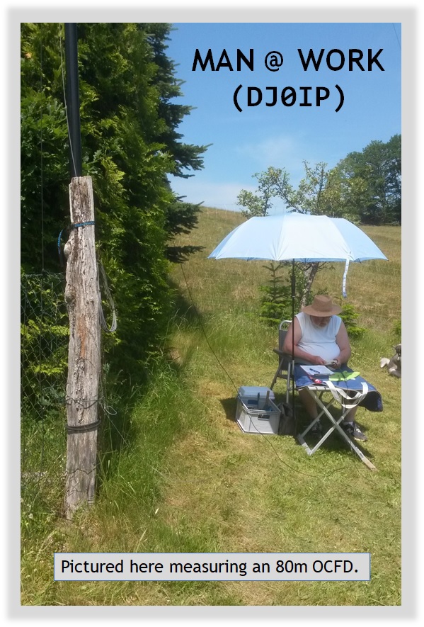
The antennas I describe below evolved from an intensive study of the Off-Center-Fed Dipole (OCFD) & its Common Mode Current (CMC) characteristics over a period of 5 years (2012 - 2017).
During that time, I made over 1500 field measurements on various OCFD antenna configurations.
I didn't always have sunshine; often I was measuring in the rain, snow and/or wind.
The Off-Center-Fed-Dipole antenna has had a two-prong reputation for many years. Although many users swear by it, just as many (or more) have complained of its problems with Common Mode Current. Most Antenna Guru's despise it.
In 2012 I was determined to learn why this was and to see if I could correct it. In addition to solving the CMC issues, I also wanted to see if I could get it to work on the 15m band - IMO one of the most interesting DX and contest bands.
At the end of 5 years of research, work, trials and tribulations, I believe I have found something approaching the Holy Grail for the OCFD antenna!
THIS is how I do it:
2. INTRODUCTION
On this page I will show you how to build an 80m OCFD that works most bands without the need for an antenna matchbox.
- Note: Only a few hundred kHz of the 80m band can be used without an antenna matchbox. To cover the full 80m band, you will need a matchbox.
- Note: Unlike most other OCFD antennas that you see, this version has low SWR on 15m. (Exception: 33.3% Split)
You may find that I do some things differently than what you have seen, heard, or read elsewhere. My antenna designs definitely works as I describe them below.
- Those claiming 15m does not work with an 80m or 40m OCFD haven't done their homework.
- If you wish to discuss this, I invite you to join our OCFD antenna
group:
- There you will find 1300+ members willing to discuss this with you.
- Join Group: https://groups.io/g/ocfd
THE OCFD ANTENNA IS A COMPROMISE
If you expect to have perfect SWR on all bands, you have set a false expectation level.
The OCFD has good SWR on many bands, usuable SWR on a few bands, but there is always a band or two with very high SWR.
As with most multi-band antennas, you will likely have to use an antenna matchbox on some of the bands.
BEFORE continuing, I encourage you to do a Master Clear about everything you have ever heard or read about this antenna . . . and start fresh!
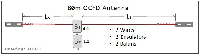
After 90 years, it is time to bring this Windom-derived OCFD antenna into the 21st Century! Specifically, we will:
- Move the feedpoint.
- Define and use a new type of Balun.
- Add a feature to enable placing 80m resonance anywhere we like.
3. PLANNING 'YOUR' 80m OCFD ANTENNA
There are several different 'good' places along the 1/2 wavelength of wire to feed your 80m OCFD. Exactly 'where' you place the feedpoint determines which bands will be covered.
As you can see in the chart below, no feedpoint position enables a low SWR on all bands. Therefore it is necessary to determine your favorite bands of operation and select the feedpoint position that best matches your set of bands.
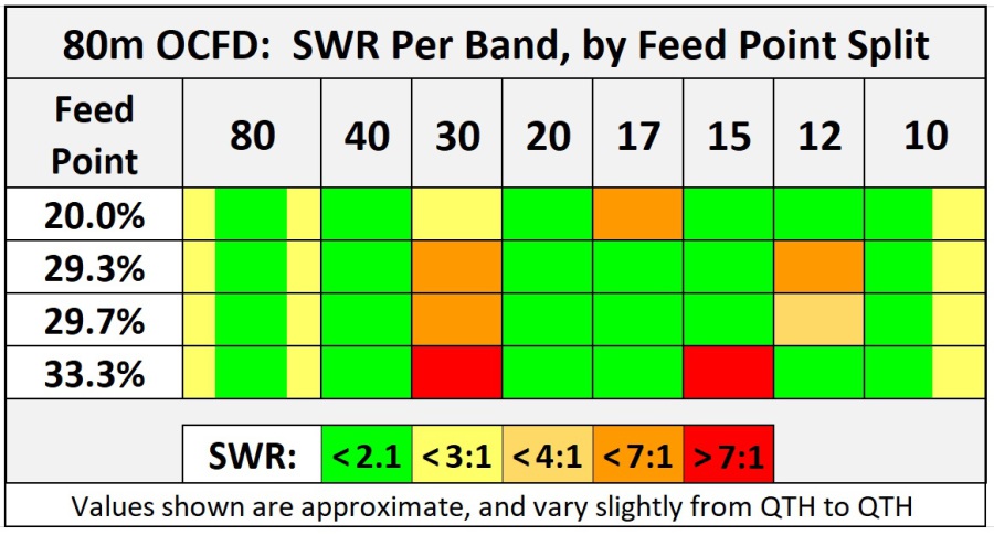
- In general, most transceivers can operate in the 'GREEN' areas without the need for an antenna matchbox (or ATU).
- Some transceivers can operate in the 'YELLOW' areas without an ATU, but most will need either their built-in ATU or an external antenna matchbox.
- 80 and 10m bands are very broad. They are shown here as 'Green-and-Yellow'. You will likely have good SWR over about half of the band but will need an ATU for part of the band.
- Operation in the 'ORANGE' areas require an ATU, but performance is still outstanding on these bands.
- Bands marked 'DARK ORANGE' have higher SWR, but they are still quite usable with an antenna matchbox.
- Bands marked in 'RED' have very high SWR and should not be used, even with an antenna matchbox, unless you reduce the transmitted power level significantly. Otherwise you risk destroying the BALUN.
HOW LONG SHOULD THE ANTENNA BE?
The answer to this question cannot be expressed in a NUMBER. It must be expressed in a DESCRIPTION:
- The overall length must be cut such that the Frequency of Minimum SWR, hereafter depicted as 'SWRmin', is 40 kHz BELOW the 80m band.
REASONS:
- The exact length overall varies, depending on the size of wire and the consistency of its insulation (if any). It can vary as much as 40cm (16 in.) - thus no length can be given unless it is accompanied by a specific wire type.
- The ham band 'ranges' are not true harmonics of each other. See the table below.
- The OCFD antenna is NOT a harmic antenna. See the table below.
"THEORETICAL" HARMONIC FREQUENCIES:
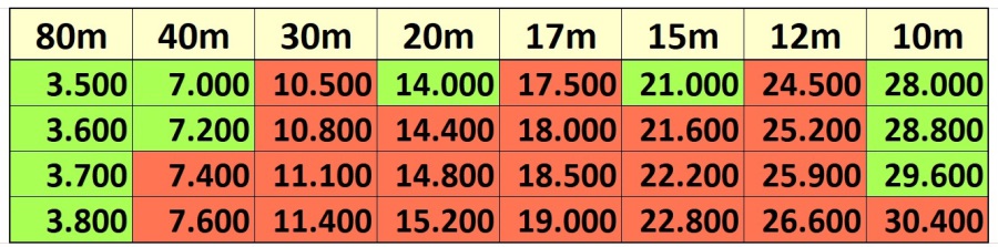
As can be seen here, as we raise the 80m SWRmin frequency, "exact" harmonic frequencies soon reside ABOVE the harmonic bands.
"MEASURED" HARMONIC FREQUENCIES:
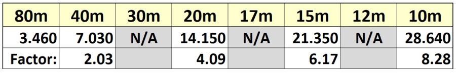
This chart reflects typical real-life SWRmin frequencies.
- Note: No frequencies are shown for the WARC bands becasue SWRmin on these bands does not fall within the band.
The multiplication factors are roughly '2.03'/'4.09'/'6.17'/'8.28' intsead of 2/4/6/8, because "End-Effect" affects each band differently than it affects the others.
Your mileage may vary!
This skews SWRmin higher in frequency on the higher harmonic bands.
Now lets return to OVERALL LENGTH:
The Dipole Formulas:
- Feet: 492 / f x .95 . . . (492/3.460) x .95 = 135.1 feet
( f is frequency in MHz )
- Meters: 150 / f x .95 . . . (150/3.460) x .95 = 41.18m
Keep in mind that these lengths can vary, depending on the type and size of wire used, as well as the characteristics of the surrounding terain.
As always, it is best practice to cut the wires slightly longer than needed, then fold back the excess wire at the insulator, wrapping the excess tightly around the wire leg:
TIP: fold back about 25cm (10 in.) on the short end and 50cm (20 in.) on the long end. Do not cut the excess wire off until you have finished the final tuning of the antenna.
80m Resonance? 3.460 MHz? :-(
Don't Worry! We will adjust 80m resonance in the last step of the construction of the antenna. We shall see how to place 80m SWRmin on any frequency we choose, without changing resonance on the higher bands.
4. THE BALUN
The BALUN is 'THE' most critical component of the 80m OCFD antenna.
It is the lynchpin for success . . . or the cause of failure in ALL 80m OCFD's.
The OCFD antenna has inherantly a lot of Common Mode Current (CMC). The farther away from the center of the antenna you place the feedpoint, the stronger the CMC.
The primary task of the balun is to prevent RF current from flowing along the outer surface of the coax shield when it returns to ground.
- A good balun successfully blocks [almost] all of the CMC.
- A poor balun blocks some, but not all of the CMC.
- A bad balun fails to block the CMC. Unfortunately many OCFD antenna vendors are selling antennas with this kind of balun.
If the balun fails to block all of the CMC, the RF current flowing on the outside of the coax effectively converts the coax into part of the antenna. This changes its resonance; the frequency of SWRmin skews higher up the band. It also causes bogus SWR readings and several other bad things.
Besides these negative influences on the antenna, CMC on the feedline often causes interference to consumer products in the house (yours and the neighbor's house), and when receiving, it often picks up unwanted noise from these consumer devices, raising the noise level in the receiver by several S-Units.
The ability of a balun to block (impede) CMC depends on its Common Mode Impedance (CMI) at the frequency of transmission.
The amount of CMC on an OCFD antenna is maximum on its
fundamental frequency, and that is where a lot of CMI is required.
The problem with most baluns built for and sold for use in OCFD antennas is, it is assumed they need 'good' CMI across the entire hf spectrum. The baluns are optimized for that. This results in insuficient CMI on the fundamental frequency where it is needed most.
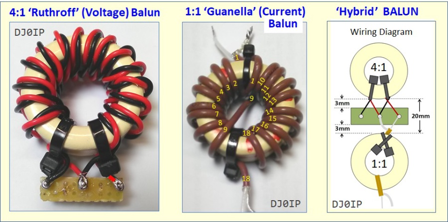
The popular consensus is, we should always use a Current Balun in our antennas - not a Voltage Balun. At the same time, there is an additional need to step up the impedance from 50 Ohms to 200 Ohms. This is normally accomplished using a 4:1 transformer balun. Consensus dictates using a 4:1 'Guanella' (Current) balun, rather than a 4:1 'Ruthroff' (Voltage) balun. Sounds good; won't work.
The problem is, the best dual-core 4:1 Guanella balun has only about half as much Common Mode Impedance (CMI) as is needed for an 80m OCFD. Another (better) solution is needed.
The 1:1 Guanella balun has at least twice as much CMI as the 4:1 Guanella. Thus it is the better choice for blocking CMC. This leaves us with the problem of stepping up the impedance. To do this, we shall use a 4:1 Voltage balun. It works fine as a step-up transformer.
We shall combine these two baluns to create a Hybrid Balun; a very special Hybrid Balun. Caution: At this time (JAN 2021), US vendors selling 'hybrid baluns' are not selling the same balun as we must use here. BUYER BEWARE!
Before defining the hybrid balun, we must first know how much power the antenna will be used with. In this document, I will describe two versions; one for about 600 Watts, the other for 1 kW (ratings for SSB/CW). I have not built any for higher power levels and do not wish to speculate on their build.
The 600 Watt 4:1 Ruthroff balun will be built on either an Amidon FT-140-61 or a Ferroxcube TX36/23/15-4C65 Toroid.
The 1000 Watt 4:1 Ruthroff balun will be built on an Amidon FT-240-61 Toroid.
It will be wound with 15 turns of Teflon-insulated wire, either Bifilar or Twisted-Pair. I prefer to use twisted pair because it is easier to twist two wires together than to tape bifilar together. I used 18-AWG wire for the 600w version and 16-AWG wire for the 1kW version.
The 1:1 Guanella will be built on either an FT-140-43, or an FT-240-43 (hi-pwr).
- The 600w version is wound with 18 turns of 2.5mm (dia.) Teflon-insulated Coax (i.e.,
RG-316). If only 200 watts or less is all that is required, you may substitute RG-174.
- If you wish to run 600w in Digi-Modes, you must stack two FT-140-43 cores together and wrap them as one thick core.
- Alternative: Ferroxcube TX36/23/15-4A11 instead of the FT-140-43.
- The 1 kW version is wound with 18 turns of
RG-142 (Teflon-Insulated) coax. 18 turns will fit but you must wind the turns as close together as possible onto the FT-240-43 core.
- The coax MUST be Teflon insulated. I often use DXW50 (from DX-Wire) instead of RG-142. It has a slightly lower power rating, but is more flexible than RG-142 and easier to work with.
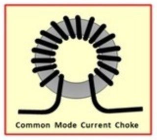
Note: These Guanella baluns may be wound with all of the turns in one direction, simply winding around the entire core - as shown here on the right -->
Or they may be cross-wound using the W1JR/Reisert method as shown below in the photo of the 1:1 Guanella balun.
600 Watt BALUN CONSTRUCTION:
Note: the white Feroxcube Toroids shown here have a coating of Epoxy over the Ferrite. The Amidon Toroids work just as well, but for the picture, the Feroxcube's show better contrast.
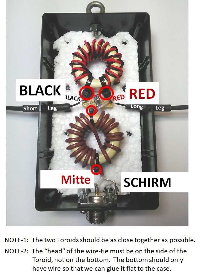
600 Watt SSB/CW Hybrid BALUN
Here you see the 4:1 "Ruthroff" (Voltabe) Balun on top and the 1:1 "Guanella" (Current) Balun on the bottom.
The white styrofoam in back was added for better photo contrast.
Translation:
- Mitte: Coax Center Wire
- Schirm: Coax Shield
These cores are both Ferroxcube Toroids, which have a thin layer of Epoxy painted onto the ferrite surface. Amidon FT-140-xx cores work just as well.
The version shown here is only good for 200 Watts in digital modes. With higher power, it heats up and SWR slowly creeps up.
For 600 Watts Digi-Modes, you must use a stack of 2 identical cores in the Guanella balun.
HIGH POWER HYBRID BALUN (1kW SSB/CW):
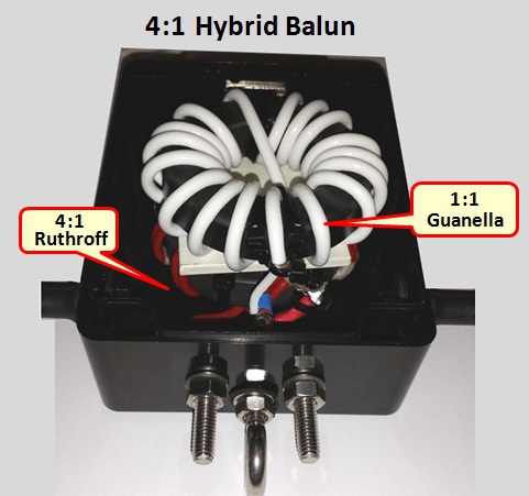
NOTE: This version was built with the two baluns mounted "Piggy-Back" - one on top of the other. If you look closely, you can see a white spacer between the two baluns. This is necessary. The one shown here is Teflon, but it can also be FR4 (Epoxy Board).
Wiring is exactly the same as shown above in the lower power version of this balun. In case you are wondering, the white Coax shown here is not RG-142, but something similar. It is DXW50; also Teflon insulated coax - it has a slightly lower power rating but good enough for 1 kW. I chose it because it is more flexible than RG-142 and much easier to work with; and I don't need the higher power rating for this balun.
5. TUNING THE ANTENNA
First, you must adjust the overall length to achieve SWRmin on 3.460 MHz. Contrary to standard practice, the OCFD antenna MUST NOT be tuned by adjusting its overall lengths. If you do that, you will certainly lose coverage of one or more bands.
Before beginning the tuning process, it is important to determine the SWR curves across each of the bands it is to cover. The best way to do this is with a scanning analyzer, such as the RigExpert AA-30, AA54, etc.
Please study the SWR curves near the bottom of this page:
- YOUR SWR curves should look similar to the ones shown there.
Then scan your antenna according to the following table:
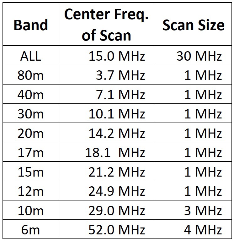
- Save EACH band's data file to the analyzer.
- Then transfer it to your computer, giving each file a filename that reflects its band.
- Use the data shown in the "Band" column of the table on the left to name the files.
- Tip: When comparing two bands, it helps to print one band to a piece of paper, then compare it to the other band on the computer screen
If you do not have access to a scanning analyzer, then you must manually (and patiently) conduct several SWR measurements on each band. Record your results in one of the charts below:
Use this chart to record the SWR values across each of the bands to be covered.
SWR Chart.xlsx
Microsoft Excel-Dokument [15.6 KB]
Use this version if you do not have access to Excel.
SWR Chart.pdf
PDF-Dokument [120.2 KB]
AFTER analyzing the SWR curves across each band, you will have a stake-in-the-ground as starting point for adjusting the antenna.
How to proceed: Begin by adjusting the overall length for SWRmin = 3.460 MHz.
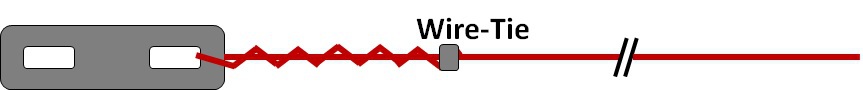
To do this, you should shorten the Long Leg and Short Leg proportionally to their Split-Ratio. Example (assuming 20%/80% Split): If you determine you must shorten the antenna by 10 cm (or 10 in.), shorten the long leg by 8, the short leg by 2 cm (or inches). Remember: don't cut the wire (for now); just fold it back and fasten with a wire-tie.
NEXT, examine each band carefully and determine the frequency where the SWR is minimum (SWRmin). Record these onto paper.
IT IS IMPOSSIBLE for me to describe exactly how to proceed, because it can be different, depending on which feedpoint split you have chosen.
Remember, shortening the antenna raises the frequency of SWRmin, lengthening it lowers the frequency.
The problem is, different bands may need adjusting in opposite directions.
For instance, what you might see is that 20m could be a bit shorter whereas 15m could be a bit longer... or vice-versa. This is what you should look for.
Remember: it is a compromise; it will never be perfect.
Adjust for the best compromise.
Remember: If you decide to make adjustments after trimming the antenna for an SWRmin of 3.460 kHz on 80m, be sure to adjust proportionally to the split ratio.
6. ADJUSTING 80m RESONANCE
AFTER you have completed tuning for the best compromise on all bands (except 80m), THEN you can proceed to adjust the frequency of SWRmin on 80m.
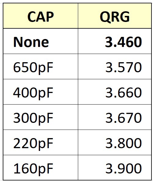
When an antenna resonates too low in frequency, it has inductive reactance. You compensate for this by adding capacitive reactance.
You must insert a capacitor in the exact middle of the antenna (50% of its overall length). The value of the capacitor determines where SWRmin will be.
Here are some approximate values, however they will only get you close. If you want to have SWRmin on 80m at an exact frequency, you will have to determine the value of the capacitor emperically. You can do this by paralleling several disc ceramic capacitors of 100 and or 50 pF (as needed).
CAUTION #1: The capacitor's peak voltage requirement is not high (3kV will do), but high voltage from static electricity will damage it. To protect the capacitor from this, you must shunt it with a high-Ohm resistor. Its value can be anything from 3 Meg. to 10 Meg. Ohms, and it should be about 3 Watts.
CAUTION #2: The REAL DANGER is high current. The capacitor should be able to handle about 1.5 Amps of current for 100 Watts, or 4 Amps for 1kW.
The exact value depends on the amount of capacitance used, and the power applied. The charts below may be used as a rough estimate:
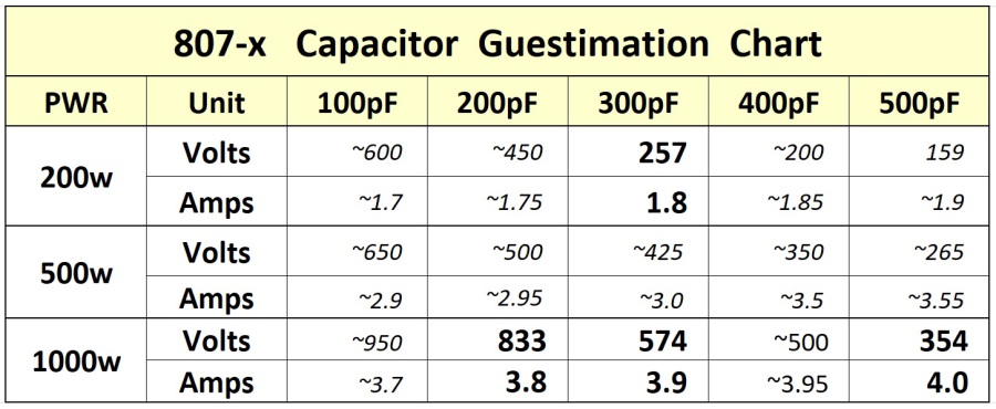
CAPACITANCE v.s. FREQUENCY CHART
As stated above, these are only approximate values.
After choosing the capacitance, consult the chart above to determine the voltage and amperage requirements.
Note: for 650 pF and 1kW, use 5A.
.
If possible, use low-loss COG (NPO) capacitors.
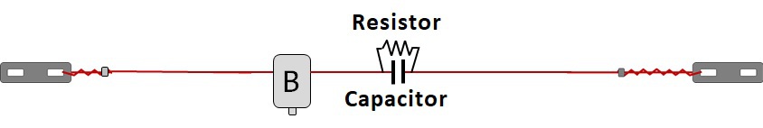
EXAMPLE of a CAPACITOR BOARD:
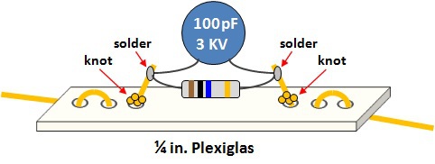
Note: The drawing above shows just one disc ceramic capacitor. For high power you should use a transmitting capacitor, however these don't offer much flexibility. Instead, you can parallel several capacitors together to obtain the desired capacitance and current handling.
Although the drawing shows Plexiglas (which works fine), I typically use "FR4" Epoxy board for these Cap boards.
After soldering the board into the antenna, you should shorten the far end of the longer leg to compensate for the wire added by the legs of the capacitor(s).
FINALLY: Re-check the SWR curves across all bands.
NOTE: For the commercial versions of my antennas, I use Power-SMD capacitors and resistors in the capacitor board. It has 3 resistors in parallel and several capacitors in parallel. I can vary the frequency of SWRmin by changing the value of the capacitors, and/or the number of capacitors used:

(This is a hybrid - drawing/photo. After adjusted, it is covered with heat-shrink tubing.)
This concludes the construction and tuning of the antenna.
The Information on this Page is <<<CONFIDENTIAl>>>
I have given you the password in confidence that you will use
this info for you own personal use and not share it with others.

N E W

A Short Video by W8JI
N E W
OCFD ANTENNA
PRESENTATION


( Info-Only; NO SALES! )
Spiderbeam on Facebook:


BRAND NEW
from Spiderbeam:

Mini "SOTA" Pole
by Rob Sherwood NC0B

(AUF DEUTSCH)


Spiderbeam FG Pole

Photo: Nischal Nethrananda

A fun film about
Ham Radio Outdoors
(not just in Tenerife)
(English & German)


(nearly) Invisible Pole

An Aerial-51
Sponsored Expedition:
INTRODUCING
Special purpose Aerials:

Ultra-Lightweight antennas for expeditions and stealth applications.
+
(other)
---------------------
UPDATES:
|
|
-----------------
LL-TUNER "S-MATCH"
added to my
symmetrical tuner page.
----------------------
PROGRESSING:
LOTS OF NEW CONTENT IN THE SECTION:


Since JAN-2013
*******************