
Short Top Band (160m) Antenna
FOR HAMS WHO DON'T HAVE 80m (260 ft.) OF SPACE
Much of the information on this page is based on 4 articles written by Alfred Kluess, DF2BC, for the German magazine CQDL. All pictures and translated excerpts are presented here with written permission from Alfred and the DARC Verlag.
Each page concludes with a DOWNLOAD of the original article (in German language).
EFFICIENCY AND PERFORMANCE ARE RELATIVE . . .
Nobody is claiming that this is an antenna of choice; to the contraty. I hope I never have to resort to using an antenna like this on Top-Band. However many hams don't even have space for this antenna. This is a low cost alternative to a magnetic loop.
This artical is about how to get maximum performance out of very small antennas in
a very small space.
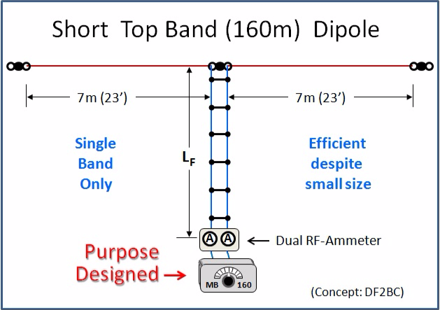
DESPITE what you may have read elsewhere, short antennas such as the one pictured here do indeed work relarively well on 160m, provide you provision for the high voltage and high current involved.
This is possible to achieve on a case by case basis, but not as a generically reproducable solution.
If you want to do this, you'll have to do your homework and build it yourself.
You cannot buy this type of matchbox but you can easily build it yourself. It has just one variable capacitor and one easy to wind coil. But it is a very special capacitor and a very hefty coil. This is necessary for the HUGE amount of current that flows through the antenna system. Just 40 to 50w of power produces up to 4 amps of RF current in the dual-Ammeter at the feedline.
The antenna described here is used by DF2BC who has limited yard space for antennas. He uses this antenna efficiently on several bands from 160 thru 20m, but he has three different matchboxes, one for Top Band, one for 80m and one for 40/30/20m. Each matchbox is purpose-designed for use with "this" antenna. These are not general purpose matchboxes.
THE DOWNSIDE: You CANNOT cover all bands with a single matchbox. Each of the three matchboxes (which I will describe in detail) uses a totally different circuit than the others.
THIS PAGE discribes the 160m Top Band Antenna Coupler as it was described in an article by DF2BC in the May, 2011 issue of "CQDL" magazine on pages 332 & 333. The title of the article was "Parallelkreis-Koppler fuer 160m".
THE FOLLOWING IS A ROAD MAP
On how to build yourself a Short
Efficient 160m Antenna System.
This is not a Plug-n-Play project.
Unfortunately you cannot simply buy this solution. You will have to build it yourself or pay someone to build this for you. If executed properly, this antenna system will enable you to have 5-9+ signals for NVIS work and maybe even work the occasional DX.
This is the specific antenna that is being used with the matchbox described below:
Whether or not you consider this antenna efficient will depend on what you compare it to.
For a tiny antenna, the antenna system (antenna + matchbox) is relatively efficient.
Compared to a full size (260 ft.) dipole, it is not.
AGAIN I MUST STRESS THAT YOU CANNOT BUY A MATCHBOX THAT WILL HANDLE THIS.
As you will read below, the coil must be made of thick wire, (13 or 12 AWG) in order to handle the enormous RF current without too much loss. The variable capacitor must be a purpose-built, split-stator transmitter capacitor. This enables connection of both wires to non-moving parts of the capacitor. It also helps reduce the influence of stray capacitance from the operator's hand while tuning the matchbox.

MB-160
This is not your
father's matchbox,
though it may be what
your grandfather used!
This purpose-built link-coupled, parallel matchbox is quite capable of coping with the high voltage and high current incurred on 160m when used with the short antenna shown above.
Though limited to 100w of power, this antenna system will give you a very respectable signal on Top Band.
Beauty is in the eyes of the beholder.
In my eyes it is beautiful!
It is important to note that this link coupled matchbox galvanically seperates the input from the output.
This type of circuit has two advantages over all other types of circuits:
- It inherently reduces common mode current (CMC) by about 20 dB.
- It is basically a "filter tuner" which means it works as a band pass filter (BPF). It passes frequencies at or near its point of resonance, while dramatically reducing the signal strengith of 2nd or 3rd harmonic signals.
The parallel circuit used here was chosen because the antenna is so very small, its radiation resistance so very low on 160m.
If you can double the length of the antenna, it will be more efficient, but you will probably have better results switching to a series resonant circuit as used in the MB-80.
You're never going to be bending anyone's S-Meters with a short antenna system like this, but this will enable you to get on the air, usually with signal reports of 57(9) to 59(9) when working NVIS.

MB-160 SCHEMATIC
C1: 2X 300 Pf, 2kV, split stator capacitor, 2mm (5/64 in.) plate spacing. Used in series results in 150 pF, 4kV.
L1: 53 uH, 47 turns of well insulated wire, 2.5 sq.mm. (13 AWG) on a T-520-2 Toroid. Wound equally spaced covering 80% of the core - i.e. from 7 o'clock >> clockwise to 5 o'clock.
L2: "Sliding Coil" - 2 turns of double-shielded RG-58. The 2 turns of coax are wrapped slightly loose around L1, near one end. It must be loose enough to enable sliding L2 back and forth over L1. See "construction" text (below) for how to wire the coil end of the coax.
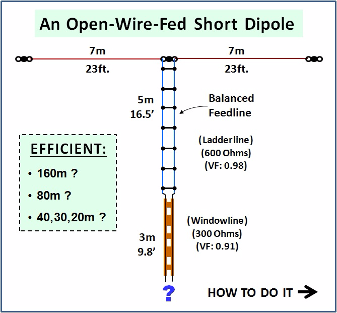
This specific matchbox was built to match the openwire fed dipole of Alfred Kluss, DF2BC. The leg lengths are shown in the drawing at the top of this page. The openwire feedline used in this specific antennas was home-brew 600 Ohm ladderline. It length was just 5m (16.5 ft.) from the feedpoint to the house. At the house it was soldered to 3m (9' 10") if 300 Ohm Windowline (i.e. WIREMAN), which connected directly to the matchbox.
It is highly unlikely that anyone building a similar antenna system will have such a short feedline. Obviously the impedance will change,and a longer feedline will significantly increase the losses, unless you can also make the two legs of the antenna longer. However in doing that, you may need a series circuit rather than a parallel circuit.
CONSTRUCTION DETAILS:
THE ANTENNA WIRE:
160m is a unique band. The typical "Skin-Effect" seen on higher bands is not so predominant on 160m due to its much lower frequency.
If you have followed several of my other pages on my web site, such as "Modern Antennas", you have seen that I normally am a fan of lightweight material so that I can hang my wire much higher, without the need for an expensive mast. I generally use WIREMAN CQ-532 wire for my wire antennas. This is insulated, stranded 18-AWG Copperweld wire.
Do NOT use Copperweld wire for the short 160m antenna!
The RF energy penetrates too deep into the wire and if there is steel inside, there will be additional unnecessary losses.
I recommend using 16-AWG or eben better, 14- or 12- AWG, even though this makes the entire antenna heavier. You should also use insulators that are able to withstand high voltage.
I can make suggestions for material available here in Europe but I am not so familiar with the availability of similar material in the states.
WIRE RECOMMENDATIONS:
- First choice for me is the DX-Wire Model "HP" (High Power). This is a well insulated, 2.5 sq.mm. stranded hard-drawn copper wire. It is approximately 13-AWG.
- Source: DX-WIRE HP
- My second choice is Fritzel "FR-9881" / also available from WiMo: "40051.25". This is the same wire that Alfred used in the coil of all 3 antenna matchboxes. It is
also 2.5 sq.mm. (13-AWG), uses 7 strands of 7 strands of 0.2mm copper wire (flexible), and has a clear PVC jacket. Though the insulation is not as hefty and UV-resistant as the DX-Wire,
it does hold up for many many years. However it stretches more than the DX-Wire.
- Source: Hofi Price List
- Source: Wimo 40051.25
INSULATOR RECOMMENDATIONS:
If you build your own ladderline using the German recommended method shown below, the insulators shown there match the spreaders and they are all you need. This would be my own first choice.
If you look closely at the pictures of the 3 matchboxes which Alfred, DF2BC designed, you will see he uses Fritzel "FR 1640-020" insulators to mount the main toroid/coil to. These same insulators make excellent insulators for this application.
- Source: Hofi Price List
I'm not sure of a good source in the US. Find something that is long and not too heavy.
You may also build your own out of Plexiglas or Epoxy Board (FR4).
FEEDLINE (TRANSMISSION LINE):
I STRONGLY SUGGEST building your own feedline for this, instead of purchasing commercial Windowline.
You should cut twe equal length of wires, one for each leg of the antenna.
Each of these wires will be used for one leg of the antenna and one side of the feedline.
That way you have a solid wire from the end-insulator, all the way to the house.
I have my favorites here too, though you can of course build these any way you like.
I show both (a German solution and a US solution) on my web page on home-brewing ladderline:
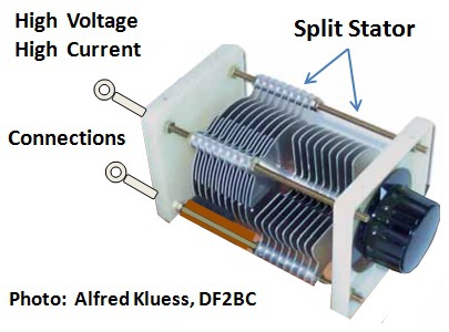
THE VARIABLE CAPACITOR
- Each stator has its own connection.
- No connection to any moving parts means less loss.
- The two stators connect capacitively through the rotor.
- The effective voltage doubles.
- The effective capacitance is half.
- The capacitor* is rated 300 pF, 2kV.
- Efectively it is used as 150 pF, 4kV.
Be sure the knob is WELL INSULATED.
Otherwise you will feel the RF when tuning the matchbox!
This type of capacitor is required for the MB-160 because it construction method eliminates the need to pass high current through sliding connections. It also doubles the amount of voltage that the capacitor can be used with.
*Possible Source: Schubert http://www.schubert-gehaeuse.de/drehkondensatoren.html
It appears to be a Schubert DKS8 (2x 13-275 pF). In any case that one will work, but depending on your antenna, you might have to parallel a 25 pF fixed capacitor across each gang.
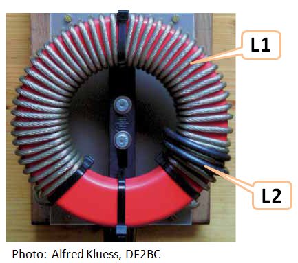
THE COILS
- L1 and L2 are wound onto a single T-520-2 (which is not cheap).
- L1 consists of 47 turns of 2.5 sq. mm. PVC-insulated, stranded wire. This is typical antenna wire sold here in Germany.
- The wire used here is 7 strands of 7 strands, which makes it very flexible. This equates to approximately 13 AWG. You may use 12 or 14 AWG wire.
- L1 begins at approximately 7 o'clock (on the clock) and ends at about 5 o'clock.
- L2 is made of 2 turns of RG-58. Use double-shielded if you can. I will describe the construction in detail below.
- L2 is wound fairly snug onto L1 but still loose enough that you can slide it back and forth to adjust for maximum RF current into the antenna. For the specific antenna used here, the final position was near the end of L1.
CONSTRUCTION OF L2
The picture below is from the 80m matchbox, but the L2 link coil is constructed in the same way for all three of the matchboxes presented in this series. This happened to be my best close-up picture.
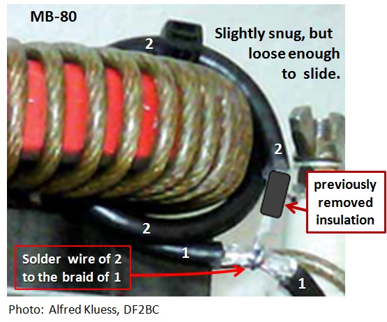
The "previously removed insulation" is a short piece of the outer coax jacket which was slipped back over the center conductor after removing the shield. See details below.
Its purpos is to make sure the shield at the end of the coax does not touch the shield at the solder joint.
IMPORTANT:
L2 WILL BE POSITIONED NEAR THE END OF L1
AS SHOWN IN THE PICTURE BELOW
(NOT AS PICTURED ABOVE)

The Toroid and two coils are mounted onto a "Fritzel" antenna insulator, enabling you to easily slide L1 along L2.
The Fritzel insulator was the defacto standard insulator here in Germany in the 1970s, 80s, and 90s.

Detailed Construction of L2:
STEPS 1 thru 5:


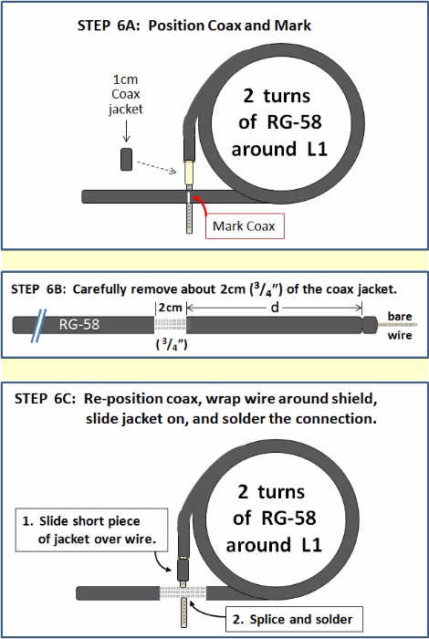
STEP 6: Determine the solder connection point where the coax will be soldered.
BEFORE YOU BEGIN, please look at the picture for STEP 6B. In STEP 6 we must determine the length of distance "d". It is not possible to say how long it is because this will depend on the size of wire that L1 is wound with.
- You will first wind two turns of this coax around L1m making sure it is slightly snug but still loose enough to slide.
- Then mark the position on the coax where the solder joint is to be.
- Next, VERY CAREFULLY cut and remove 2cm of the jacket, centered on the point where the solder connection is to be. You can mark the coax with a permanent ink, white "Sharping" (Edingstift), a piece of tape, anything.
- Finally you will re-position L2 around L1, slide the jacket over the insulation portion of the center conductor, and splice and solder the connection.
- Note: if you were unable to salvage 1cm of coax jacket when you removed it, then use something else; another piece of coax, or perhaps just use heat shrink tubing.
- The purpose is to make sure the esposed strands of the shield near the end of the coax to not make contact with the shield near the solder point.
Now procede with Steps 6A, 6B, and 6C . . .
DOWNLOAD THE ORIGINAL ARTICLE
"Parallelkreis-Koppleer fuer 160m", by Alfred Kluess, DF2BC, as published in the May 2011 issue of the DARC's CQDL magazine on page 332 and 333.
Parallelkreis-Koppleer fuer 160m.pdf
PDF-Dokument [166.6 KB]
This is an English translation of Alfred's (DF2BC) German article in the May, 2011 issue of the DARC's CQDL magazine.
Parallel Circuit Coupler for 160 m-EN.pd[...]
PDF-Dokument [370.0 KB]
I wish to express my gratitude to Alfred, DF2BC and to the DARC Verlag for permision to use their material on my web site.
More Info on the DARC Verlag is here: www.darcverlag.de

N E W

A Short Video by W8JI
N E W
OCFD ANTENNA
PRESENTATION


( Info-Only; NO SALES! )
Spiderbeam on Facebook:


BRAND NEW
from Spiderbeam:

Mini "SOTA" Pole
by Rob Sherwood NC0B

(AUF DEUTSCH)


Spiderbeam FG Pole

Photo: Nischal Nethrananda

A fun film about
Ham Radio Outdoors
(not just in Tenerife)
(English & German)


(nearly) Invisible Pole

An Aerial-51
Sponsored Expedition:
INTRODUCING
Special purpose Aerials:

Ultra-Lightweight antennas for expeditions and stealth applications.
+
(other)
---------------------
UPDATES:
|
|
-----------------
LL-TUNER "S-MATCH"
added to my
symmetrical tuner page.
----------------------
PROGRESSING:
LOTS OF NEW CONTENT IN THE SECTION:


Since JAN-2013
*******************