
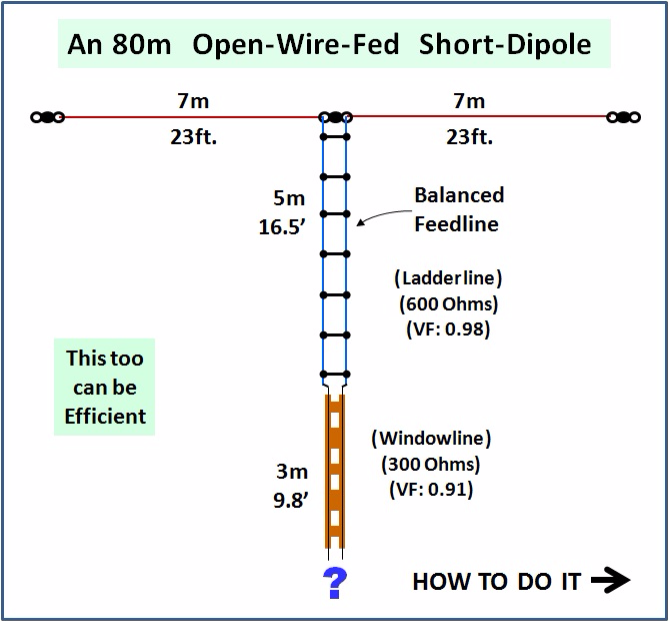
SHORT EFFICIENT 80m ANTENNA
FOR HAMS WHO DON'T HAVE 40m (130 ft.) OF SPACE
Much of the information on this page is based on 4 articles written by Alfred Kluess, DF2BC, for the German magazine CQDL. All pictures and translated excerpts are presented here with written permission from Alfred and the DARC Verlag.
Each page concludes with a DOWNLOAD of the original article (in German language).
SHORT
YET STILL
RELATIVELY
EFFICIENT
It all depends on how you match
this antenna to
your transceiver.
DO NOT EXPECT YOUR FAVORITE MATCHBOX TO WORK WITH THIS!
And don't
be afraid
to build
your own.
KEEP IT SIMPLE, FOLKS!
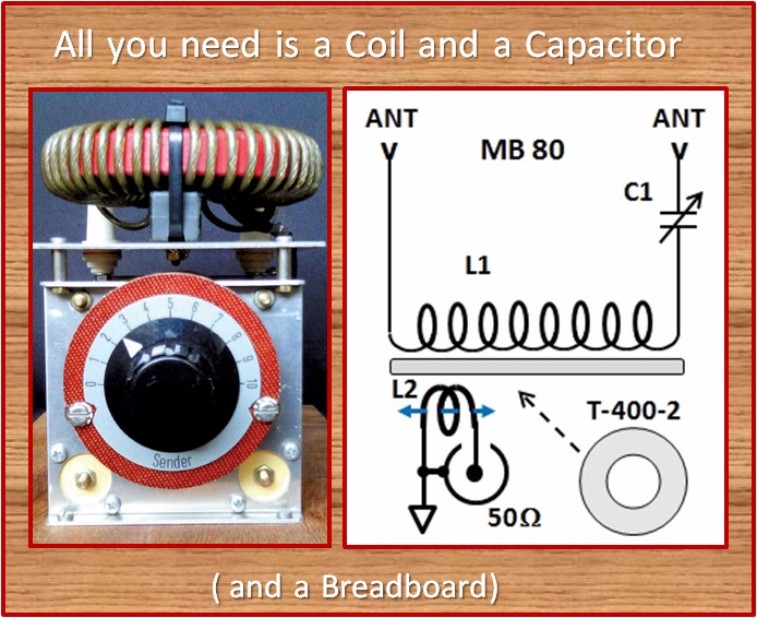
Of course it is a very special coil and a very special variable capacitor,
but with that and 5 cents worth of knowledge and understanding,
you will be on the air on 80m with 100w and a decent signal.
You're nevere going to be bending people's S-Meters with a short antenna system like this, but this will enable you to get on the air, usually with signal reports of 57(9) to 59(9) when working NVIS.
In several years or running a short, openwire fed vertical dipole (6m per leg), I have determined that this antenna (in its vertical form) was on par with my full size 80m horizontal dipole at 40 ft. This matchbox is good for this type of antenna.
With this antenna (mounted vertically) I easily work transatlantic on 80m. While it can be shown mathematically that the efficiency is not great, I can assure you that having an antenna occupying just 1 sq. ft. of ground and working DX on 80m IS FANTASTIC!
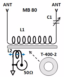
MB-80 SCHEMATIC and COMPONENTS
Because the antenna is electrically significantly longer on 80m than on 160m, we have switched to a series resonant circuit.
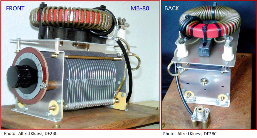
- L1 = 30 uH, 35 turns of 2.8 sq.mm. (13-AWG) wire wound on an Amidon T-400-3 Toroid. You may use 12- or 14-AWG instead. The wire itself is not critical as long as it is roughly this size. The inductance should be as close as possible (for this specific antenna). Like with the MB-160, the coil should be wound from 7 o'clock to 5 o'clock (on the clock). The wires are basically touching on the inside of the toroid and equally spaced on the outside of the toroid. See pictures of this (MB-80) and the MB-160. L1 is mounted onto a Fritzel antenna insulator with wire-ties. The insulator is strapped to the Epoxy Board.
- L2 = 2 turns of RG-58; this is built EXACTLY like L2 in the MB-160 on the previous page. DETAILS As seen in the picture, L2 mounts near the end of L1 that is not connected to C1. WARNING! Do not try to slide L2 while your are transmitting. Always cease transmitting before moving the coil. Adjust for maximum RF current into the feedline
- C1 = 200 pF, 2kV capacitor. In his matchbox, Alfread used a Schubert DK7, rated 15 to 430 pF at 2.3 kV - because that was what he had on hand.
Best of course would be a split stator (butterfly) capacitor, but then it would have to be 2x 400 pF at 1.5 kV.
- ALTERNATIVE: Use a 100 pF high voltage capacitor in parallel with a 100 pF high voltage fixed capacitor. You can switch it in and out with a banana jumper. See 40-30-20m matchbox on the next page for example of switching with banana jumpers. REMEMBER: we also have high current here so a HV disc ceramic capacitor will not work. You find HV capacitors for this application on ebay.
- SO-239: Alfred did not use a rear panel, so he mounted the SO-239 on short stand-offs, simply screwing it into the breadboard using wood screws.
- ALTERNATIVE: Simply us a longer piece of coax, perhaps 3 ft. long, and solder a PL-259 onto the end. Be sure to use some kind of strain relief to prevent force from being applied on L2. A wood screw and wire-tie will suffice.
- Antenna Connectors: Alfred used ceramic stands-offs. These are fine but expensive and difficult to find. If you mount an Epoxy-Board on top of C1 as Alfred did, you can use High-Power Banana Jacks instead. In fact you can also simply use screws (or bolts), using the Epoxy Board as the insulator. Alfred used specific crimp-solder lugs with an opening having a perfect fit for banana plugs.
to be continued soon . . .
I know there are several people waiting for this one.
I will try to hurry. - Rick
DOWNLOAD THE ORIGINAL ARTICLE
"80-m-Serienkreis-Koppler", by Alfred Kluess, DF2BC, as published in the September 2011 issue of the DARC's CQDL magzine on pages 646 and 647.
80m Serienkreis Koppler.pdf
PDF-Dokument [359.3 KB]
I wish to express my gratitude to Alfred, DF2BC and to the DARC Verlag for permision to use their material on my web site.
More Info on the DARC Verlag is here: www.darcverlag.de

N E W

A Short Video by W8JI
N E W
OCFD ANTENNA
PRESENTATION


( Info-Only; NO SALES! )
Spiderbeam on Facebook:


BRAND NEW
from Spiderbeam:

Mini "SOTA" Pole
by Rob Sherwood NC0B

(AUF DEUTSCH)


Spiderbeam FG Pole

Photo: Nischal Nethrananda

A fun film about
Ham Radio Outdoors
(not just in Tenerife)
(English & German)


(nearly) Invisible Pole

An Aerial-51
Sponsored Expedition:
INTRODUCING
Special purpose Aerials:

Ultra-Lightweight antennas for expeditions and stealth applications.
+
(other)
---------------------
UPDATES:
|
|
-----------------
LL-TUNER "S-MATCH"
added to my
symmetrical tuner page.
----------------------
PROGRESSING:
LOTS OF NEW CONTENT IN THE SECTION:


Since JAN-2013
*******************