
Antenna Tuners
ANNECKE UNIVERSAL-TRANSMATCH
IMPORTANT NOTE: I have written permission to use all of Annecke's original publications and pictures on my web site. This permission was granted by Fred Annecke, Alfred Annecke's son.
[ 750 Watt ]
A FAMILY OF VERY ROBUST T-NETWORK MATCHBOXES
BASED ON THE CIRCUITRY OF THE ORIGINAL ULTIMATE TRANSMATCH
BY LEW McCOY, W1ICP (SK)
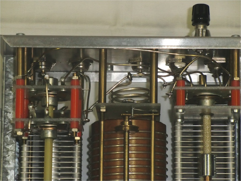
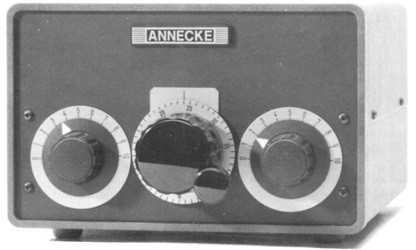 Photo: Alfred Annecke
The 750w Universal Transmatch is a German implimentation of the Lew McCoy (W1ICP) "Ultimate Transmatch" - which was sometimes also called the universal transmatch.
This design, in contrast to later designs, incorporates the dual variable capacitor (voltage divider) on the input or transmitter side of the T-Network. Most modern versions do not use the dual capacitor.
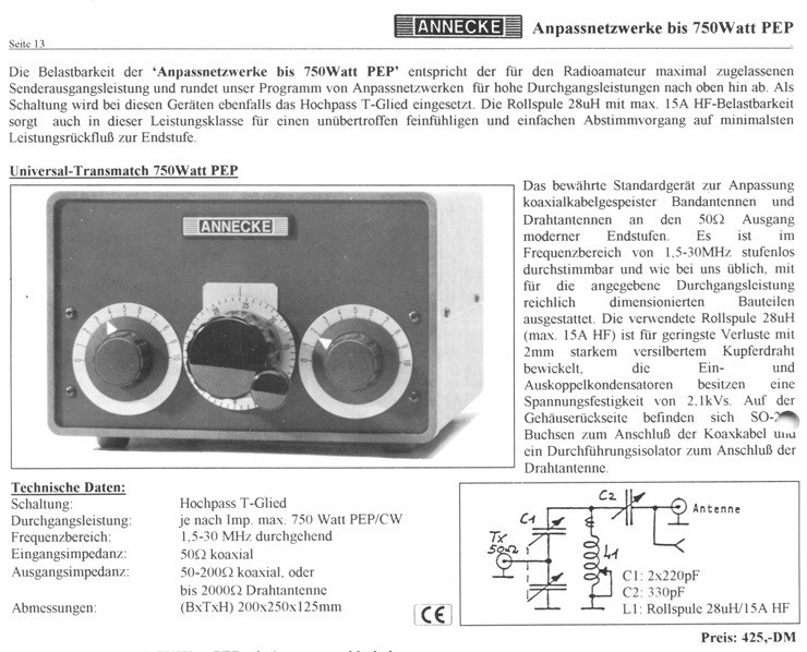
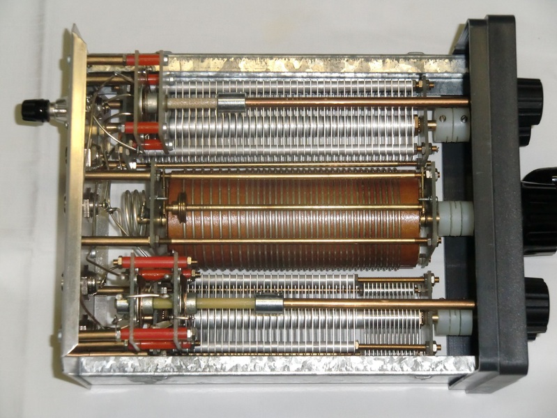
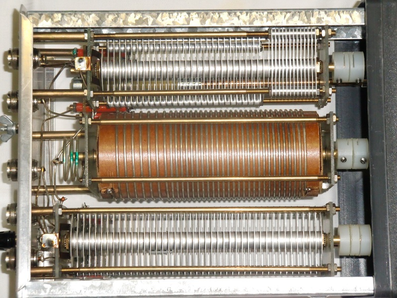
The circuitry used here is identical to that of the 300w Universal-Transmatch (Type 228), except the variable capacitors have wider plate spacing and the Roller Inductor is rated at 15A (HF) current. In contrast, the 300w version's inductor was rated at just 3A.
Different Versions / Models
- Simple Matchbox
- Matchbox with Antenna Selection Switch
- Matchbox with Antenna Bypass Switch
- Matchbox with Antenna Switch and Bypass Switch
SPECIFICATIONS:
- Bands: 160 to 10m
- Power Rating: 750 Watt PEP/CW
- Impedance Matching Range:
- 50 to 200 Ohms Coaxial-Fed Antennas
- 50 to 2000 Ohms Longwire Antennas
- Size (Width/Heigth/Depth): 20 x 12.5 x 250 cm (8" x 5" x 10")
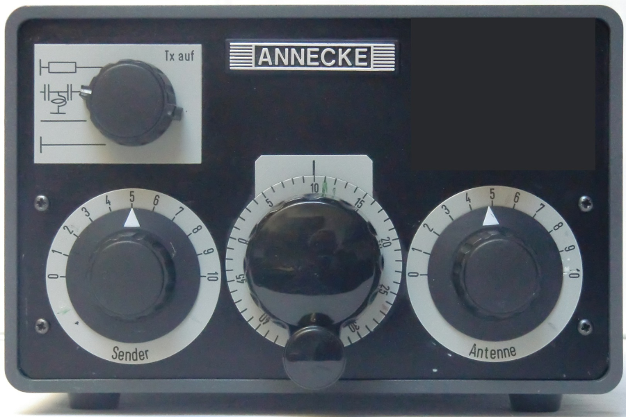
The unit shown here was the basic Universal-Transmatch, and formed the foundation for 3 other models, which added the following options:
- Antenna Switch
- Network Switch (Bypass Switch)
- Antenna Switch and Network Switch
Each of these is explained below.
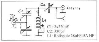
Basic Schematic:
This is the classical (original) Ultimate-Match by W1ICP. Note how C1 has two sections, ganged together. What you don't see from the schematic is that the top section of C1 has about twice the voltage rating as the bottom section.
All of the 750w Universal-Transmatch matchboxes as well as the original 300w Universal-Transmatch had this double-capacitor on the 50 Ohm side. Later (modern/current) versions of the Ultimate Transmatch by most other manufacturers no longer use a dual-capacitor. Later versions of the Annecke 300w version also used the single variable capacitor. See more on that on the 300w Universal-Transmatch page.
The biggest drawback of this basic version of the Universal-Transmatch is, it was always in the antenna feedline. There was no switch to bypass it. As I said, this was the basic version. Other versions are shown below.
Here is an original catalog excerpt describing the 750 Watt Universal-Transmatch:
 ...Picture Courtesy of Frank Reijnen
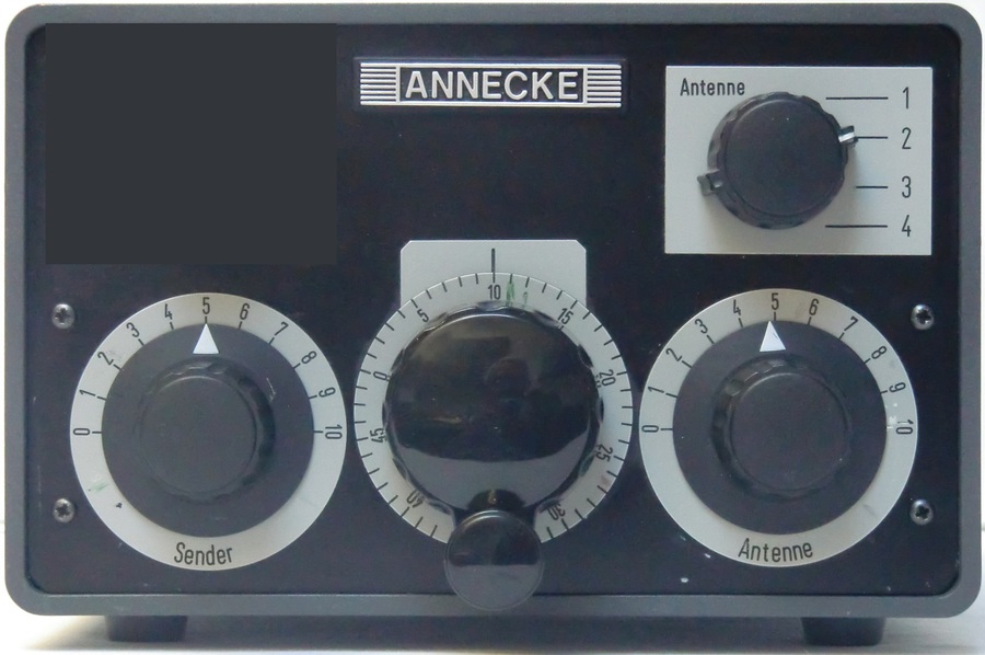
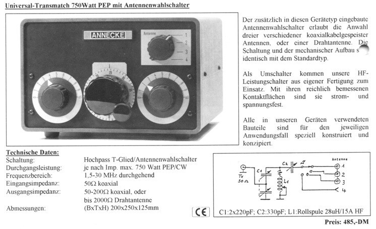
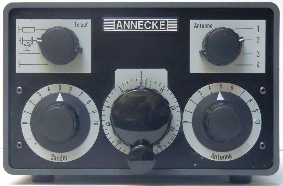
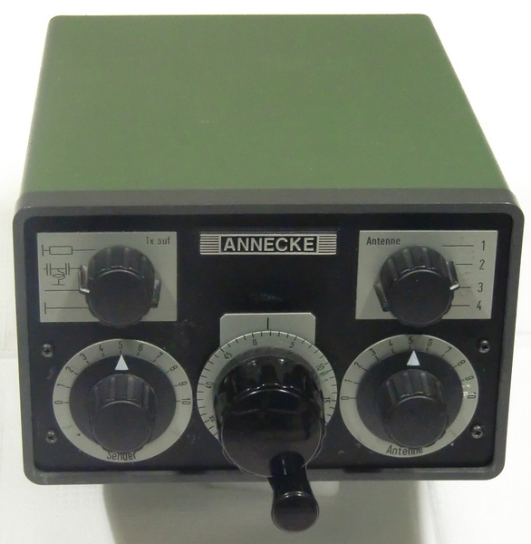
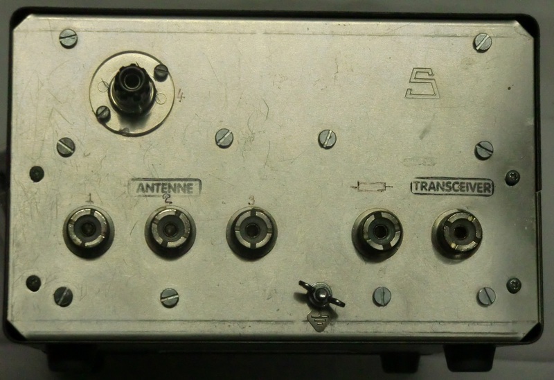
750w Universal-Transmatch with Antenna Selection Switch.
This version offered the ability to switch between 4 different antennas, 3 coax fed and one longwire antenna.
Other than that, the circuitry was exactly idential to that of the basic model.
The antenna switch is a "nice to have" option, but a more important, basic functionality was still missing; the ability to bypass the matchbox completely when the antenna's impedance is good enough without a matchbox.
Positions 1, 2, & 3 were for coax-fed antennas. Position 4 was for longwire antennas.
Here is an original catalog excerpt describing this version of the Universal-Transmatch:
 ...Picture Courtesy of Frank Reijnen
750w Universal-Transmatch with Antenna Bypass Switch.
(Network Switch)
This version offered the ability to switch between the antenna with matchbox, dummy load, bypass, or ground.
Other than that, the circuitry was exactly idential to that of the basic model.
 ...Picture Courtesy of Frank Reijnen
THE TRANSMATCH FLAGSHIP:
750w Universal-Transmatch with Antenna Bypass Switch and Antenna Selection Switch.
This version offered the ability to switch between the antenna with matchbox, dummy load, bypass, or ground AND it also enabled switching between 4 different antennas. As always, the circuitry was exactly idential to that of the basic model.
This was the top of the line model.
 ...Picture Courtesy of Frank Reijnen
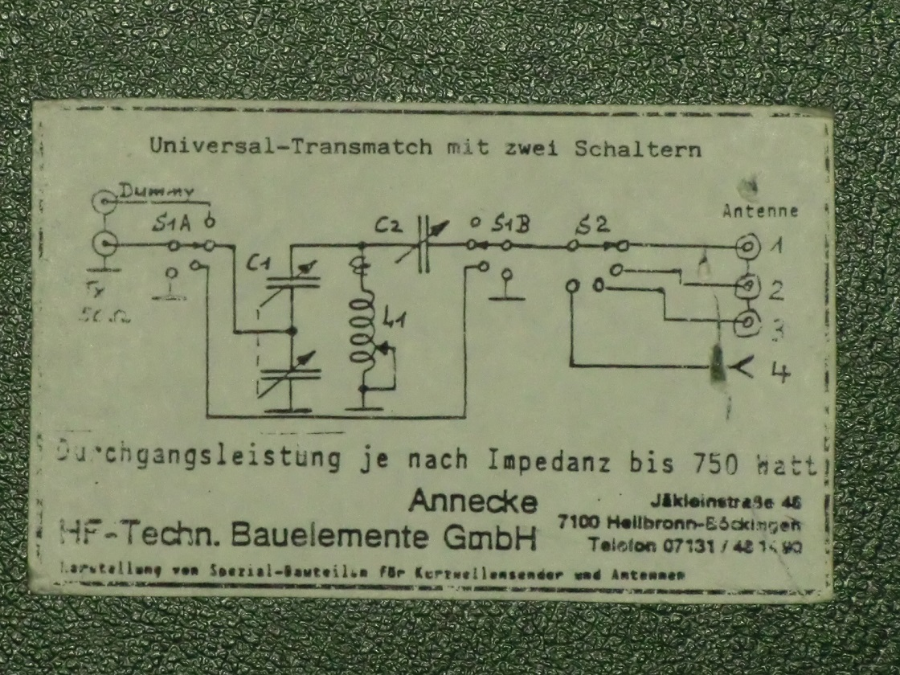
This is a picture of the schematic, which Annecke always glued to the bottom of the matchbox cabinet.
In this close-up you can see that the finish of the case was not just dark green, but kind of a hammerschlag surface.
The advantage is, it doesn't show scratches as much as a flat surface.
GALLERY:

N E W
OCFD ANTENNA
PRESENTATION


( Info-Only; NO SALES! )
Spiderbeam on Facebook:


BRAND NEW
from Spiderbeam:

Mini "SOTA" Pole
by Rob Sherwood NC0B

(AUF DEUTSCH)


Spiderbeam FG Pole

Photo: Nischal Nethrananda

A fun film about
Ham Radio Outdoors
(not just in Tenerife)
(English & German)


(nearly) Invisible Pole

An Aerial-51
Sponsored Expedition:
INTRODUCING
Special purpose Aerials:

Ultra-Lightweight antennas for expeditions and stealth applications.
+
(other)
---------------------
UPDATES:
|
|
-----------------
LL-TUNER "S-MATCH"
added to my
symmetrical tuner page.
----------------------
PROGRESSING:
LOTS OF NEW CONTENT IN THE SECTION:


Since JAN-2013
*******************