
CMC TEST - FEEDLINES
For the purpose of this test, I have chosen lightweight coax (RG-174) to run up the fiberglass pole.
Though not necessary with the super heavy duty pole I used, it would be a good thing to use this lightweight coax with smaller, lighter duty poles, such as the Spiderbeam 12m fiberglass pole.
When extending the coax, I used various lengths which I happened to have on hand. These included LMR-240 and RG8-X.
Velocity Factors . . . there are TWO!
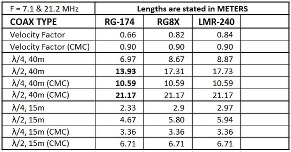
Each coax has two different velocity factors. One is well known; it is the published velocity factor of each type of coax. For instance, the VF of RG-174 is "0.66".
Unfortunately the second velocity factor is not published by the manufacturers and is unknown. This is the velocity factor between the outer surfice of the coax shield and the jacket insulation around the coax. Although it is unknown, it is commonly accepted to be somewhere in the neighborhod of 0.90 to 0.95 for most pieces of coax. For the purpose of this test I have chosen to use "0.95", and will assume all coax used in this test are the same when measuring CMC.
The first (known) velocity factor is used for calculating electrical lengths for waves traveling inside the coax.
The second (unknown) velocity factor is used for calculating electrical lengths for Common Mode Current, which travels only on the outer surface of the coax shield. Since it does not flow inside the coax, the normal velocity factor of the coax does not apply.
As a result, an electrical half-wavelength of a specific type of coax when used for measuring antenna impedances (SWR characteristics) will be one length, but when measuring Common Mode Current on that same type of coax, the electrical half-wavelength will be longer.
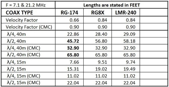
Table of Feedline Lengths
(Once again there are TWO; one shows lenghts in meters, the other shows lengths in feet.)
.
WHY THESE 3 TYPES OF COAX?
Simple answer: These were the types of coax I already had in my shack, available for the test.
The RG-174 was used on the pole for reasons stated above.
Whether I used RG8X or LMR-240 depended on the length I had available vs. the length needed for the particular test.
Lengths of Interest for the Test
- 11 Meters (36' 1")
- 1/2 (electrical) Wavelength
- 1/2 (physical) Wavelength
- 1/4 (physical) Wavelength
WHY THOSE LENGTHS?
"11 Meters" was chosen because this is a convenient length to reach from the feedpoint of the antenna, to the bottom of the pole and give the operator about 1 meter of spare feedline to connect to the transceiver. This was deemed to be a typical portable deployment.
"1/2 (electrical) Wavelength" was chosen because whenever connected to an antenna, will repeat the exact impedance of that antenna's feedpoint. This is the point we shall use to specify the basic characteristics of each antenna. For this purpose we will use the manufacturer's specified velocity factor (0.66, 0.78, or 0.82, depending on which coax we are using).
"1/2 (physical) Wavelength" is also important when measuring Common Mode Current. The amount of CMC flowing on the outside shield of a coax varies significantly according to the point along the coax at which you measure. It has been shown by G3TXQ* that one half wavelength (or multiples thereof) is the point of maximum CMC. For determining this length, we will use the assumed VF of "0.95". * http://www.karinya.net/g3txq/chokes/
"1/4 (physical) Wavelength" is also important because it is the point of minimum Common Mode Current - again as shown by G3TXQ* (same reference as above). It is interesting to see the difference between the points of minimum and maximum CMC. Again we will use the CMC VF, not the published VF for this measurement.
COAX LENGTHS:
- CX-213-0.3:....30cm...RG-213...(1')
- CX-174-11:.....11m.....RG-174...(36.1')
- CX-174-12:.....12m.....RG-174...(39.4')
- CX-8X-10:.......10'.......RG8x.......(3.05m)
- CX-240-25:.....25'.......LMR-240..(7.62m)
COAX COMBINATIONS:
Typical Portable: CX-174-11 + CX-213-0.3
1/2 λ on 40m: CX-174-11 + CX-8X-10 +CX-213-0.3
1/4 λ (CMC)on 40m: CX-174-11 + CX-213-0.3 (about 1m too long)
1/2 λ (CMC)on 40m: CX-174-11 + CX-8X-25 + CX-213-0.3 (about 1m too long)
3/2 λ on 15m: CX-174-11 + CX-8X-10 +CX-213-0.3
3/2 λ (CMC) on 15m: CX-174-11 +
CX-8X-25 + CX-213-0.3 (about 1m too long)

N E W

A Short Video by W8JI
N E W
OCFD ANTENNA
PRESENTATION


( Info-Only; NO SALES! )
Spiderbeam on Facebook:


BRAND NEW
from Spiderbeam:

Mini "SOTA" Pole
by Rob Sherwood NC0B

(AUF DEUTSCH)


Spiderbeam FG Pole

Photo: Nischal Nethrananda

A fun film about
Ham Radio Outdoors
(not just in Tenerife)
(English & German)


(nearly) Invisible Pole

An Aerial-51
Sponsored Expedition:
INTRODUCING
Special purpose Aerials:

Ultra-Lightweight antennas for expeditions and stealth applications.
+
(other)
---------------------
UPDATES:
|
|
-----------------
LL-TUNER "S-MATCH"
added to my
symmetrical tuner page.
----------------------
PROGRESSING:
LOTS OF NEW CONTENT IN THE SECTION:


Since JAN-2013
*******************