
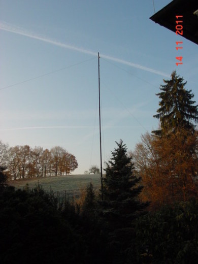
The CMC Test Mast
.
 The lower 12m of a Spiderbeam 18m fiberglass telescoping pole.
Many people treat the mast as a second thought. In reality, the mast, though low tech, is a very important piece of the antenna system. In this case we will be measuring common mode current in various antennas. By choosing a mast of fiberglass rather than aluminum or steel, we make sure the mast itself does not distort the test results.
The specific goal of this test is to evaluate the behavior of various antennas with respect to CMC, when mounted at 10m height, a typical height used for portable operations.
Because I will be testing several antennas of various weights and raising and lowering antennas often, I chose to run with a very strong, heavy duty fiberglass pole from Spiderbeam, the 18m telescoping fiberglass "Spiderpole".
I have removed the top 4 segments of the pole and only extended the top segment a few cm. I then mounted a pulley at the 10m level.
The pole shown here is next to my house.
It is the exact same type of pole I used at the antenna test site.
.
A Good Ground (Earth)
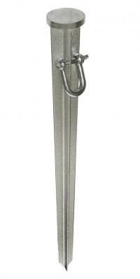
FOR TESTING AT THE ANTENNA POLE:
Directly under the pole I have driven a galvanized steel stake similar to the one shown on the right, about 50cm into the ground
The ground wire is 6mm stranded copper, about 1m long with a huge aligator clamp (jumper cables clamp) attached to the end.
Of course this is not a perfect ground, but I think it is representative of what one would typically have at a temporary/portable site.
FOR TESTING AT THE "WORST CASE CMC" POSITION:
This operating position was set up just inside the door of our Summer House.
The bathroom is immediately on the right.
I ran a 1.5m cable to the cold water pipe in the bathroom.
The plumbing is of all metal (no plastic) because it was built about 40 years ago.

N E W

A Short Video by W8JI
N E W
OCFD ANTENNA
PRESENTATION


( Info-Only; NO SALES! )
Spiderbeam on Facebook:


BRAND NEW
from Spiderbeam:

Mini "SOTA" Pole
by Rob Sherwood NC0B

(AUF DEUTSCH)


Spiderbeam FG Pole

Photo: Nischal Nethrananda

A fun film about
Ham Radio Outdoors
(not just in Tenerife)
(English & German)


(nearly) Invisible Pole

An Aerial-51
Sponsored Expedition:
INTRODUCING
Special purpose Aerials:

Ultra-Lightweight antennas for expeditions and stealth applications.
+
(other)
---------------------
UPDATES:
|
|
-----------------
LL-TUNER "S-MATCH"
added to my
symmetrical tuner page.
----------------------
PROGRESSING:
LOTS OF NEW CONTENT IN THE SECTION:


Since JAN-2013
*******************