
HAIRPIN MATCH
When building Low Band Vertical antennas, or even Inverted-L antennas for 160/80m, you will often find that the feedpoint impedence is much lower than the theoretical value of 36 Ohms. In fact if it is base loaded it may be closer to 10 Ohms.
The "the Hairpin Match" is a simple and easy way to fix this problem.
I don't like this name, and would prefer to call it a "shunt match" because it is really just a simple coil shunted across the coax. However there is no point in trying to change this trend of calling it a Hairpin. It is already widely known as "Hairpin Match" and some companies even sell ready-made coils for this purpose, under that name.
Quarter-wave vertical antennas mounted on the ground typically have an impedance of about 36 Ohms (assuming no ground losses). However shorter verticals (e.g., base loaded with a coil, or top loaded with top hat wires) typically have an impedance close to 10 Ohms, and at best 20 Ohms. Typical ground losses in the real world are about 10 Ohms, giving you a total feedpoint impedance of 20 to 30 Ohms.
Often, especially in portable operations, the impedance appears higher but that’s because the ground losses are higher and the SWR meter is seeing the sum of the antenna’s own impedance and the additional ground losses.
Reducing ground losses by improving the radial network will result in a more efficient antenna, but the SWR will be even higher. You can address this by deploying one of the following options.
Here are your options:
- Do Nothing (use it as it; not a good option except maybe on 160m)
- Use a Matchbox in the Shack. (not the best option, but it works)
- Use a 4:1 UNIN (this might work, depending on the impedance, but it can be expensive for high power)
- Use an LC Network with a series Inductor and a Capacitor shunted to ground on the coax side of the L.
- Use a Hairpin Match (simplest option)
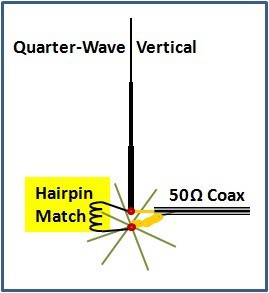
This is what the hairpin match looks like:
The coil is made of thin copper tubing or soft-drawn copper wire, about 2mm (AWG #12) in diameter for medium power levels, and 3mm (AWG #8) to 4mm (AWG #6) diameter for high power.
Wrap about 10 to 12 turns of copper wire (or copper tubing) onto a temporary form (like a wine bottle) such that its diameter is about 7 to 10cm (3 to 4 inches). After winding the coil, remove the wine bottle.
IMPORTANT:
Do not drink the wine until after winding the coil ! ;-)
TUNING:
- Measure and record the SWR
- Push the turns of the coil closer together and see if the SWR improves or gets worse
- Pull the turns farther apart and check if the SWR gets worse or improves.
- Adjust for best SWR.
- Note: if spread too far apart and still not perfect, remove 1 or 2 windings from the coil.
- Note: if squeezed tightly together and still not perfect, add 1 or 2 windings to the coil.
PICTURES
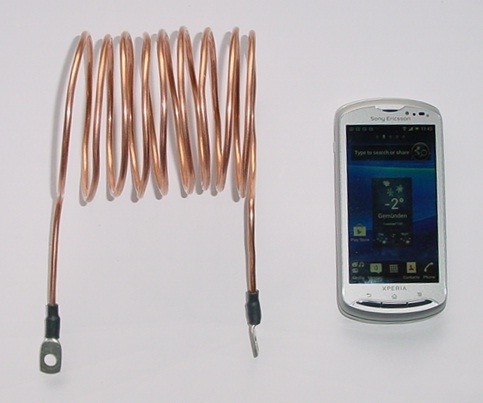

The coil should intentionally be wound with too many turns, then shortened in the field to obtain the length which gives you the best match. Fine tuning is accomplished by spreading the turns farther apart, or pushing them closer together.
Coil Details: I used about 4 meters of thick copper wire, 3.5mm diameter (AWG-7 or 8), wrapped on the end of a wine bottle. The bottle is removed after the coil is completed. The wire was purchased at a local home improvements store.
NOTE: If you use solder lugs, solder only one lug onto the coil when you first build it. AFTER you have trimed the coil, you can solder the second lug onto it.
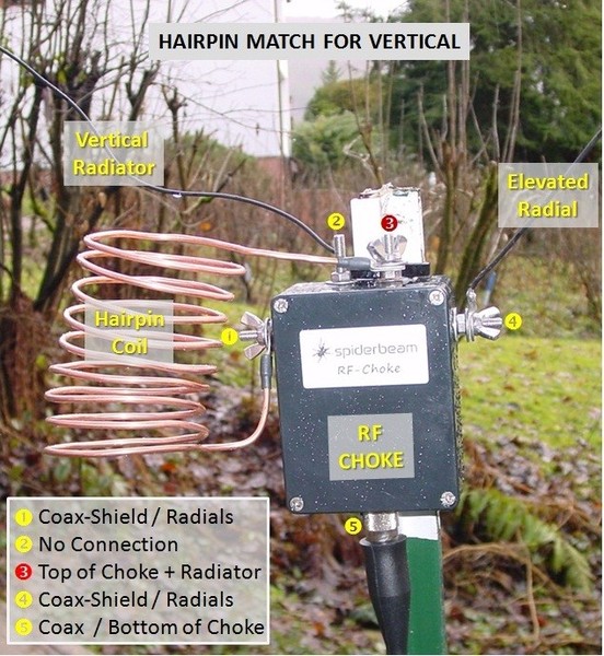
The RF-Choke shown in the picture is optional. It may not be necessary, but it does not hurt to always use it. You may also use the "beads over coax" type of RF Choke if you prefer, but on 160m, you need a lot of beads.
For a description of this choke, see: RF-CHOKE .

N E W
OCFD ANTENNA
PRESENTATION


( Info-Only; NO SALES! )
Spiderbeam on Facebook:


BRAND NEW
from Spiderbeam:

Mini "SOTA" Pole
by Rob Sherwood NC0B

(AUF DEUTSCH)


Spiderbeam FG Pole

Photo: Nischal Nethrananda

A fun film about
Ham Radio Outdoors
(not just in Tenerife)
(English & German)


(nearly) Invisible Pole

An Aerial-51
Sponsored Expedition:
INTRODUCING
Special purpose Aerials:

Ultra-Lightweight antennas for expeditions and stealth applications.
+
(other)
---------------------
UPDATES:
|
|
-----------------
LL-TUNER "S-MATCH"
added to my
symmetrical tuner page.
----------------------
PROGRESSING:
LOTS OF NEW CONTENT IN THE SECTION:


Since JAN-2013
*******************