
1:1 (Current) Choke/Balun
(Note: 1:1 Maxwell Choke for RG-174 . . . see bottom of this page.)
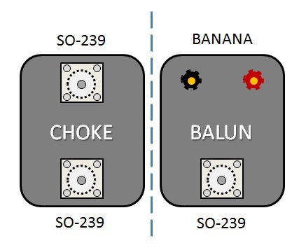
CHOKE VS BALUN
The only difference between a
1:1 Guanella Choke
and a
1:1 Guanella Balun
is the connector(s)
on one side.
Of course the balun does not have to use banana jacks. It can use anything you want it to use. Often it is eyebolts and sometimes only wires.
Both have exactly the same primary task: to keep common mode current from reaching the feedline. More accurately, "to maintain the balunce in the differential current flowing inside of the coax." The Balun typically inserts directly into a dipole or other antenna, whereas the choke is usually used in a coaxial line.
The third case is when using a balun between an unbalanced Antenna Matchbox (tuner) and openwire feedline (balanced line or ladder line). In this case we insert the 1:1 Guanella balun with a very short coaxial stub to the ATU. NOTE: contrary to popular belief, a 4:1 balun is the WRONG device to choose for this task. REASON: HERE.
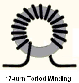
HOW TO WIND A CHOKE
Honestly, this is the simplest thing to build in the entire world! As seen in the picture on the right, simply wind the coax around a toroid core and the choke itself is finished. All that remains is to add the connectors.
Tip: If using a PL-259, it is best to solder one onto the end of the coax before winding. Do not solder both because this makes winding through the small hole difficult. Once the choke is finished, soldere the other connector(s).
Looking at this particular choke, how many turns of coax pass through the inside hole? ANSWER: 17.
Even though the first and last piece of coax passing through the hole do not make a full loop, they still count as a full turn.
When we speak of turns on a core, we really mean "number of passes through the hole."
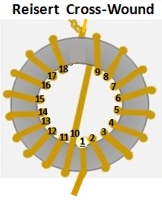
W1JR WINDING METHOD
Joe Reisert, W1JR designed a method to cross-wind the turns of wire or coax onto a toroid core. Notice how the coax winds in one direction (bottom center, upwards towards the right), then crosses back over to the bottom center, then winding upwards and left. Although this looks totally different than the simple single-direction shown in the picture above, electrically it is exactly identical. OK, in my example, this choke has one more turn than the one above, but other than that, they are exactly the same for the purpose of choking common mode current.
The cross-over also counts as one turn (in this case turn 10) because it passes through the hole.
THE REASON for using the Reisert method is, for mechanical reasons, sometimes we want to two ends of the coax to exit opposite sides of the toroid core. Notice how one exits down, the other up with this method, whereas in the standard method (above) both ends of the coax exit to the bottom.
THAT IS THE ONLY SIGNIFICANT DIFFERENCE!
USE WHICHEVER HAPPENS TO WORK BEST FOR YOU.
Simple Maxwell Choke for RG-174
Here is a simple to build, Maxwell Choke for 80-10m, made of RG-174. You may easily run 150 Watts through it.
This choke uses Ferroxcube Toroids, type CST 8.3/3.5/10/3S4 with a permeability of 1700. You may substitute similar ferrite beads from Amidon or Fair-Rite.
Important is that the size of the hole in the ferrite beads fits fairly snug over the coax.

N E W

A Short Video by W8JI
N E W
OCFD ANTENNA
PRESENTATION


( Info-Only; NO SALES! )
Spiderbeam on Facebook:


BRAND NEW
from Spiderbeam:

Mini "SOTA" Pole
by Rob Sherwood NC0B

(AUF DEUTSCH)


Spiderbeam FG Pole

Photo: Nischal Nethrananda

A fun film about
Ham Radio Outdoors
(not just in Tenerife)
(English & German)


(nearly) Invisible Pole

An Aerial-51
Sponsored Expedition:
INTRODUCING
Special purpose Aerials:

Ultra-Lightweight antennas for expeditions and stealth applications.
+
(other)
---------------------
UPDATES:
|
|
-----------------
LL-TUNER "S-MATCH"
added to my
symmetrical tuner page.
----------------------
PROGRESSING:
LOTS OF NEW CONTENT IN THE SECTION:


Since JAN-2013
*******************