
SPIDERBEAM CONSTRUCTION TIPS
Building a Spiderbeam is really QUITE EASY, but there is a lot of repetitive work.
As a result, it usually takes you about 20 to 25 hours to build the beam if you work slowly and double-check your work as you go.
The Portable version takes a couple of hours more because you have to glue the Velcro strips onto the fiberglass spreaders and wait for them to dry.
The three steps which require a little bit of caution and skill are:
- Building the driven elements and feedlines
- Building the balun.
- Proper adjustment of the center-hub to the mast.
Here are more detailed instructions plus lots of additional tips:
PAGE CONTENTS:
- READ ME FIRST: CENTER HUB
- WIRE ELEMENT CONSTRUCTION
- BALUN CONSTRUCTION
- MOUNTING HD WIRE ELEMENTS TO SPREADERS
- FINAL ASSEMBLY OF THE SPIDERBEAM
- INSTALLATION OF FIBERGLASS SPREADERS
- GUY ROPES
- MOUNTING THE BALUN
- POSITIONING ELEMENTS
- PVDF MONOFIL HORIZONTAL GUY LINES
- WORKING WITH KEVLAR ROPE
- CAUTION: TRANSPOSED DRIVEN ELEMENT FEEDLINES
- INSTALLATION IN HIGH-WIND LOCATIONS
- FINDING ROTATION ON MASTS
- PREVENTING WATER FROM STANDING ON TOP OF BALUN
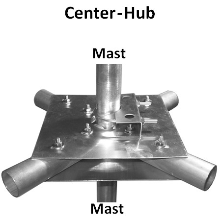
1) READ ME FIRST: CENTER HUB
This is the MOST CRITICAL step in the assembly process:
Page 18, paragraph 3.1.1 : Mounting the Vertical Mast.
This step is the one that users get wrong the most often!
Here is a file the clearly shows how to do it right and what many users get wrong when assembling their Spiderbeam:
This files shows you THE MOST IMPORTANT step in assembling and erecting a Spiderbeam.
Center Hub.pdf
PDF-Dokument [196.3 KB]
And here is a file showing a simple tip for assembling the hub:
This document shows you a better way of inserting these small tubes into the larger tubes.
Inserting_Tiny_Tubes.pdf
PDF-Dokument [108.8 KB]
2) Wire Element Construction
Note: Wire elements should not be measured when the elements are mounted on the fiberglass spreaders. Lay the element to be measured on the ground in a straight line, and then use a long tape measure to measure the lengths. Measuring with a short "yard-stick" or "ruler" will result in inacurate measurements. It is best to do this with 2 people.
This file contains step-by-step instructions (with pictures) for constructing the driven elements of the Spiderbeam.
DE-Construction-EN.pdf
PDF-Dokument [1.0 MB]
These are step-by-step instructions including pictures, for building the parasitic elements.
Constructing the Parasitic Elements 5-Ba[...]
PDF-Dokument [775.5 KB]
This file contains drawings showing how to build all 14 elements of a 5-Band Spiderbeam. Elements for other versions of the Spiderbeam are built in exactly the same way, but have different lengths. (See tables of lengths for other models in the Construction Guide.)
5-Band Spiderbeam Element Lengths.pdf
PDF-Dokument [410.0 KB]
3) BALUN CONSTRUCTION
This file gives you step-by-step instructions for building the special Spiderbeam Balun.
Spiderbeam Balun Construction_Eng.pdf
PDF-Dokument [904.7 KB]
This file contains step-by-step instructions for constructing the special Spiderbeam balun. This is the German version of this file.
Spiderbeam Balun Bauanleitung.pdf
PDF-Dokument [744.0 KB]
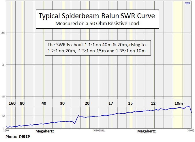
This chart shows the SWR curve of a typical Spiderbeam Balun across the HF Spectrum.
Typical Spiderbeam Balun SWR Curve.jpg
JPG-Datei [90.2 KB]
4) Mounting HD Wire Elements to Spreaders
The instruction manual is a bit confusing on this. It shows you how to mount the elements to the Portable Yagi using Velcro, but how to mount the elements to the HD Yagi is much farther in the back of the manual. This document is an excerpt from the book, showing details for the 5 Band HD Yagi.
Mounting HD Elements to Spreaders.pdf
PDF-Dokument [250.9 KB]
5) FINAL ASSEMBLY OF THE SPIDERBEAM
This documents give additional information for mounting the fiberglass spreaders onto the pole and mounting the wire elements onto the spreaders. It may also be used as a guide for the 3-Band Yagi; the procedure is the same.
Final Assembly 5-Band Spiderbeam.pdf
PDF-Dokument [293.9 KB]
6) INSTALLATION OF FIBERGLASS SPREADERS
This document show how to install the spreaders and why we do it that way.
Proper Installation of the Fiberglass Sp[...]
PDF-Dokument [202.1 KB]
This drawing shows exactly where to place the Rubber Rings.
Mounting Rubber Rings.pdf
PDF-Dokument [211.8 KB]
7) GUY ROPES
This Tip shows exactly where the Guy Ropes attach.
Guy Rope Placement.pdf
PDF-Dokument [137.4 KB]
This document describes an "OPTIONAL" additional support for fastening the Top Kevlar Guy Ropes of the Spiderbeam. It is not necessary for the Bottom Kevlar Rope Supports
Guy Rope Supports.pdf
PDF-Dokument [294.5 KB]
8) MOUNTING THE BALUN
This is additional information showing where the balun is located.
Mounting the Balun.pdf
PDF-Dokument [164.1 KB]
This document shows how to connect the 5 driven elements to the balun.
BalunConnect.pdf
PDF-Dokument [91.6 KB]
9) POSITIONING ELEMENTS
This drawing shows exact element placement onto the fiberglass spreaders, assuming the use of a 45mm Standpipe. If you use your own center mast with a diameter of 40 to 50mm, you may use these instructions. If you use the 35mm Standpipe, the first element will be 1 cm closer to the center of the mast.
5-Band Element Placement on FG Tubes.pdf
PDF-Dokument [258.4 KB]
This is additional information showing how the driven element is mounted to the fiberglass spreaders. This shows the portable version with Velcro securing the elements. The position is the same for the HD version, but hose clamps secure the elements.
Position of Driven Elements.pdf
PDF-Dokument [111.6 KB]
Although very simple, this is often misunderstood. This drawing helps to understand exactly how to mount the 15m driven Element.
15m Driven Element.pdf
PDF-Dokument [243.8 KB]
These two drawings help explain how to position the first driven element when using the 45mm or the 35mm Spiderbeam Standpipe for the center mast.
Element Spacing.pdf
PDF-Dokument [155.2 KB]
10) PVDF MONOFIL HORIZONTAL GUY LINES
This is additional information showing how to string the PVDF horizontal guy lines.
Step 3.1.2 - PVDF Guy Loop.pdf
PDF-Dokument [149.8 KB]
11) WORKING WITH KEVLAR ROPE
This is additional information showing how to prepare the ends of Kevlar Rope before using it.
Working with Kevlar.pdf
PDF-Dokument [404.7 KB]
12) CAUTION: DO NOT TRANSPOSE DRIVEN ELEMENT FEEDLINES
This describes a common mistake many people make when attaching the Driven Element feedlines to the balun.
SPIDERBEAM PROBLEMS - Transposed.pdf
PDF-Dokument [77.7 KB]
13) INSTALLATION IN HIGH-WIND LOCATIONS
This explains the mod in the file above.
Reducing Spiderbeams Lateral Motion in t[...]
PDF-Dokument [283.1 KB]
This Mod was proposed by Tino Pavic, VK3EGN. It is a simple, low-cost mod that will significantly reduce the fiberglass arm movement in strong winds.
Top-Stay Mechanical Mod.pdf
PDF-Dokument [252.1 KB]
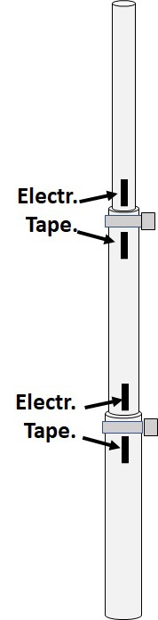
14) FINDING UNWANTED ROTATION ON MASTS
If you suspect two or more of your mast's segments are rotating within each other, but don't know which ones, here is a method to find out.
Place strips of electrical tape above and below each clamp, making sure they are lined up vertically.
Then if the segments rotate within each other, you can easily spot which ones are rotating.
If it is just one or two joints, try placing a second clamp at that position.
CAUTION: NEVER put oil on the aluminum mast segments for the purpose of making them telescope easier. They will telescope easier with oil, but they will be constantly rotating between segments!
15) PREVENTING WATER FROM STANDING ON TOP OF BALUN
When it rains, water can sometimes accumulate on the top of the balun, causing a high-impedance short between the top two connection bolts. This can result in high SWR. This tip shows how to prevent this.
CAUTION: Do not replace the PVDF monofil lines with other types of rope. Rope will also soak up water and detune the antenna. Use only PVDF monofil for this.
This tip shows 2 steps for preventing water from accumulating on top of the balun when it rains. Standing water can cause the SWR of the antenna to rise.
Prevent Water Standing on Balun.pdf
PDF-Dokument [89.1 KB]

N E W

A Short Video by W8JI
N E W
OCFD ANTENNA
PRESENTATION


( Info-Only; NO SALES! )
Spiderbeam on Facebook:


BRAND NEW
from Spiderbeam:

Mini "SOTA" Pole
by Rob Sherwood NC0B

(AUF DEUTSCH)


Spiderbeam FG Pole

Photo: Nischal Nethrananda

A fun film about
Ham Radio Outdoors
(not just in Tenerife)
(English & German)


(nearly) Invisible Pole

An Aerial-51
Sponsored Expedition:
INTRODUCING
Special purpose Aerials:

Ultra-Lightweight antennas for expeditions and stealth applications.
+
(other)
---------------------
UPDATES:
|
|
-----------------
LL-TUNER "S-MATCH"
added to my
symmetrical tuner page.
----------------------
PROGRESSING:
LOTS OF NEW CONTENT IN THE SECTION:


Since JAN-2013
*******************