
Pole Assembly
(and disassembly)
DISASSEMBLY IS VERY EASY (when you are not trying)!
All you have to do is remove the wrong cap (the bottom cap), and then holding the other end of the collapsed pole (top cap still on), sling the pole around you horizontally and watch all of the segments fly out of the pole and scatter around the yard! (hi)
Normally, nobody does this on purpose, but you'd be surprised how many people have done this by accident (including me)!
Pole Segments

Spiderbeam telescoping poles are made up of multiple segments.
The are 12 segments in the 12m and 18m poles and 15 segments in the 26m pole.
We count the segment beginning with the bottom segment as number 1. The top segment is number 12 (or 15).
When standing upright, the top of the pole is the thinner part and the bottom of the pole is the thicker part.
Except for a small portion on the bottom, the pole segment has been painted with a glossy black paint. This gives the pole additional protection from ultra-violet light, although the fiberglass itself is basically UV-resistant.
Note that the lower 4 or 5 inches (10 to 12 cm) of the pole segment are rough (paint removed).
THIS IS THE FRICTION LOCK. --> --> --> --> -->
FRICTION LOCKS are activated by pulling two adjacent segments apart and at the same time, twisting them in opposite directins.
Apply a medium amount of force, but do not use too much force. Using too much force makes it difficult to later detract the pole segments.
FRICTION LOCKS are de-activated by pushing two adjacent segments together and at the same time twisting them in opposite directins.
If you are unable to free to adjoining segments, see the page on Stuck-Segments.
Re-Assymbly of Pole Segments
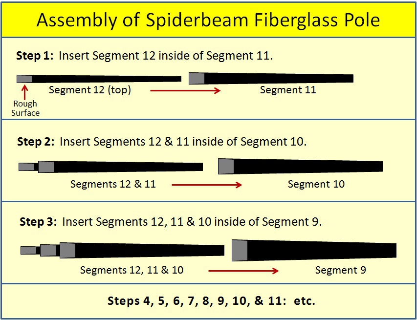
The Spiderbeam telescoping fiberglass poles are very simple to re-assemble if you do it correctly.
You begin with the top segment (#12) and insert it into the bottom of the sebment below it (#11).
MAKE SURE THAT THE ROUGH SURFACE of both segments are at the same end.
Next, insert these two segments into segment nr. 10, as shown in Step 2 on the right.
Continue as shown in the picture.
A larger picture is available in the download below.
DOWNLOAD
Assembly of Fiberglass Poles.pdf
PDF-Dokument [170.8 KB]
This is a step-by-step of a safe and reliable means of erecting an 18m Spiderbeam fg pole. You may use the same procedure for erecting the 12m fg Pole.
Installation 18m fg pole.pdf
PDF-Dokument [536.7 KB]

N E W

A Short Video by W8JI
N E W
OCFD ANTENNA
PRESENTATION


( Info-Only; NO SALES! )
Spiderbeam on Facebook:


BRAND NEW
from Spiderbeam:

Mini "SOTA" Pole
by Rob Sherwood NC0B

(AUF DEUTSCH)


Spiderbeam FG Pole

Photo: Nischal Nethrananda

A fun film about
Ham Radio Outdoors
(not just in Tenerife)
(English & German)


(nearly) Invisible Pole

An Aerial-51
Sponsored Expedition:
INTRODUCING
Special purpose Aerials:

Ultra-Lightweight antennas for expeditions and stealth applications.
+
(other)
---------------------
UPDATES:
|
|
-----------------
LL-TUNER "S-MATCH"
added to my
symmetrical tuner page.
----------------------
PROGRESSING:
LOTS OF NEW CONTENT IN THE SECTION:


Since JAN-2013
*******************